Configuring
S7-300 Programmable Controller Hardware and Installation
4-42 A5E00105492-01
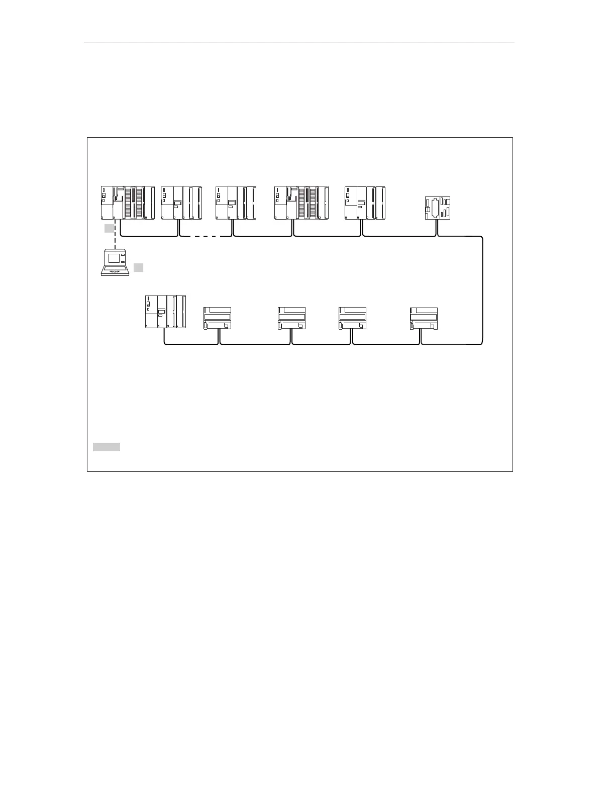
Example: PROFIBUS subnet
The figure below shows you the block diagram of a PROFIBUS subnet.
**Connect via spur lines to MPI only during Commissioning/Maintenance (with MPI address = 0)
0 ... x PROFIBUS addresses of nodes
S7-300 with
CPU 31x-2 DP
as DP master
ET 200M
11
7
8910
2
3
4
56
S5-95U
ET 200BET 200B
À
À Terminating resistance on
ET 200M
ET 200M
ET 200M
ET 200B ET 200B
* 2 = Default PROFIBUS address for DP master
0
À
PG**
3
0 ... x MPI addresses of nodes
SF
BUSF
DC5V
DC5V
FRCE
RUN
STOP
SIEMENS
SF
BUSF
DC5V
FRCE
RUN
STOP
SIEMENS
S7-300
12
Figure 4-16 Example of a PROFIBUS Subnet
 Loading...


