Testing functions, Diagnostics and Fault Elimination
S7-300 Programmable Controller Hardware and Installation
10-28 A5E00105492-01
Byte y+1 contains the code for diagnostic
interrupt (01
H
)
Byte y+1 contains the code for process
interrupt (02
H
)
The diagnostic data contain the 16 bytes of status
information from the CPU. The figure below shows
the allocation of the first four bytes of diagnostic
data. The next 12 bytes are always 0.
You can program 4 bytes of interrupt information for
the process interrupt. You pass these four bytes in
STEP 7 to the master using SFC 7 "DP_PRAL" .
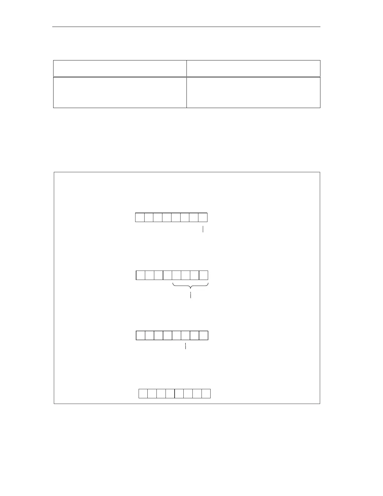
Bytes y+4 to y+7 for diagnostic interrupts
The figure below shows the structure and content of byte y+4 to y+7 for diagnostic
interrupts. Data in these bytes correspond to the contents of data record 0 of
diagnostic data in STEP 7 (in this case, not all bits are used).
0: CPU mode RUN
1: STOPCPU mode
Indentification for transfer
memory address area
Bytey+7
0: Modules o.k.
1: Module fault
Bytey+6
Bytey+5
Bytey+4
7 6543210BitNol
0000000
7 6543210BitNo.
00001011
00000 00
00000000
76543210BitNo
7 6543210BitNo.
Figure 10-11 Byte y+4 to y+7 for Diagnostic/Process interrupts
 Loading...


