4 - 32
ICP-B6 Connections and Ratings
The ICP-B6 module can be used in four
different ways:
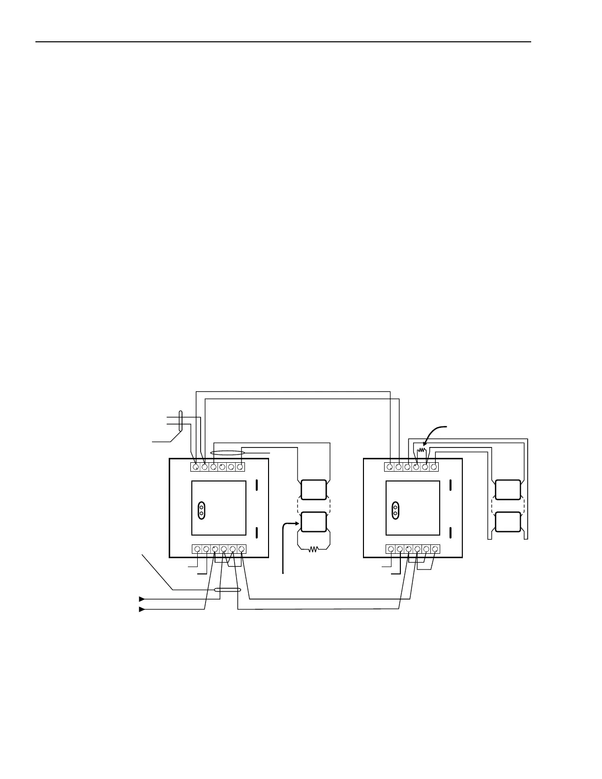
1. Using the ICP-B6 as an NAC Module
This notification appliance application
uses the principle of polarity reversal
when there is an alarm. The figure
below shows the polarity connection in
a supervisory condition. When using
the ICP-B6 as a supervised NAC output
module with notification appliance
devices, cut jumper JP2. Refer to
Compatible Notification Appliances
P/N 315-096363.
When used as an NAC module, the
output circuit is power limited. The
ICP-B6 maximum current is 1.5A at 24
VDC. If the 24 VDC is lost or the NAC
line is broken or shorted, the trouble
condition INPUT DEVICE RESPONSE
TOO LOW displays at the MXL/MXLV
control panel. See the Line Resistance
chart on the previous page for the
allowable line resistance for each
ICP-B6 output circuit.
ICP-B6 Used as a Strobe Module
++
+
+
+
+
-
-
-
-
--
POWER
LIMITED
STYLE Y
STYLE Z
15K, 1/2W, 5% EOL RESISTOR
P/N 140-820400
15K, 1/2W, 5%
EOL RESISTOR
P/N 140-820400
SUPERVISED STROBE ACTIVATION
SUPV: 9VDC, .5mA
ACTIVATED: 24VDC, 1.5A MAX
POLARITY SHOWN IN SUPV. CONDITION
ICP-B6 MODULE IS USED FOR
NAC SUPERVISION AND ACTIVATION
ICP-B6 MODULE IS USED FOR
NAC SUPERVISION AND ACTIVATION
24 VDC
NAC UNITS
SEE TABLE 1
DC INPUT RATED
24 - 27.3 VDC FWR
SUPV: 12mA
ACTIVATED: 1.5A MAX
NOTE: All wiring must comply with national and local codes.
24-27.3 VDC, 18mA MAX
9 VDC, 0.5mA
24 VDC, 1.5A, POWER LIMITED
+
+
-
-
ICP-B6 ICP-B6
PROGRAM
PLUG
PROGRAM
PLUG
TB2
TB1 TB1
6
6 6
5
5 5
4
4 4
3
3 3
2
2 2
1
1 1
++++
----
ANALOG
LOOP
CONNECTION
SUPERVISED
MODULE INPUT SUPPLY
FROM PS-35, PSR-1,
OR UL LISTED POWER SUPPLY
MANUFACTURED BY ALARM-SAF
MODEL AS/PS5-BFS-24-UL
ELECTRICAL:
INPUT DC SUPPLY:
SUPERVISORY OUTPUT:
ACTIVATED:
JP2 JP2
JP1 JP1
EARTH
SHIELD
+
+
-
-
TB2
6
5
4
3
2
1
EARTH
SHIELD
Technical Manuals Online! - http://www.tech-man.com

 Loading...


