4 - 60
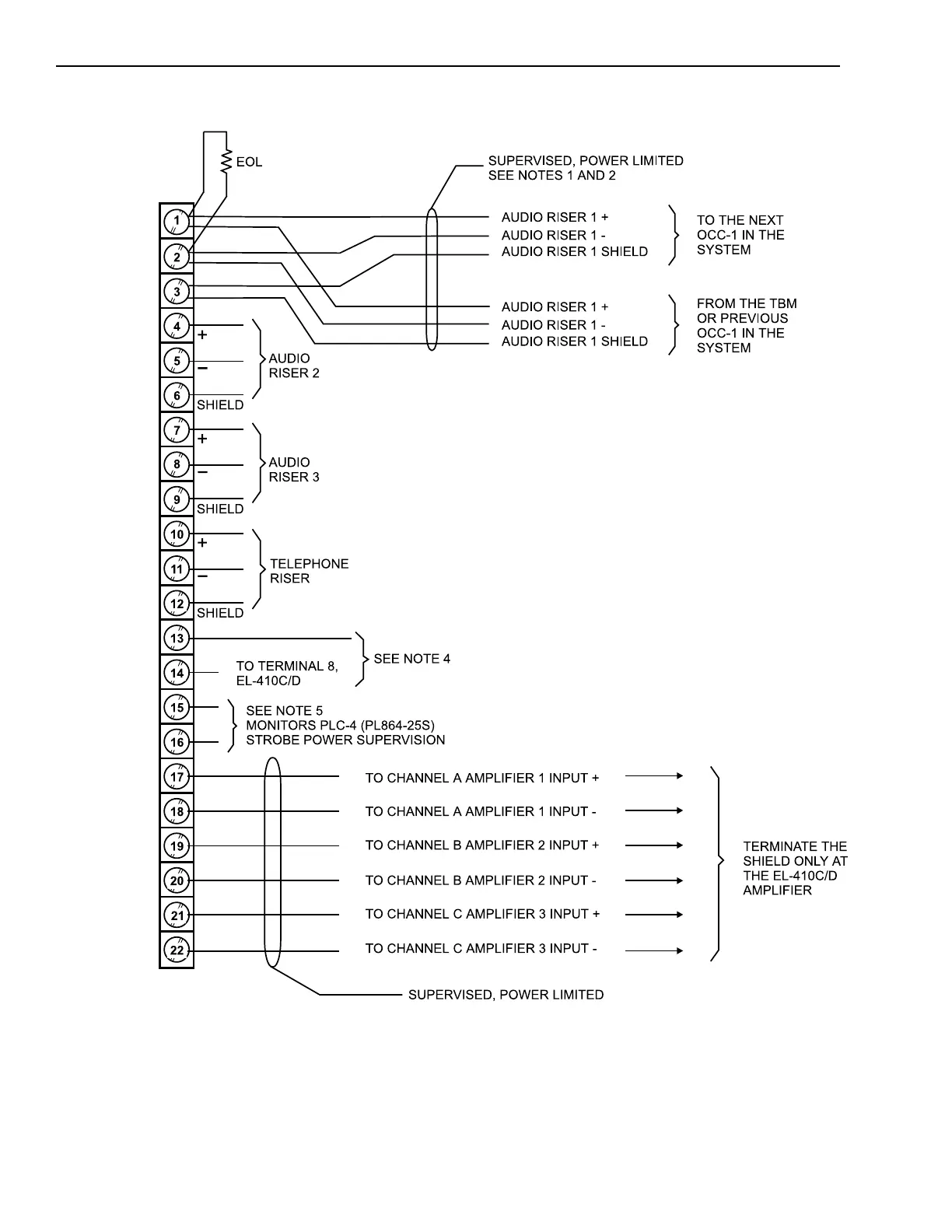
OCC-1 Connections and Ratings
Wiring the OCC-1
NOTES:
1. If this is the last or only OCC-1, terminate the inputs shown as follows:
Audio risers: 10K, ½W, 5% (P/N 140-820396).
Telephone riser: 5.6K, ½W, 5% (P/N 140-820390).
2. Maximum loop resistance: 20 ohms for telephone and audio risers.
3. Minimum wire size: 18 AWG twisted pair, shielded
Maximum wire size: 14 AWG twisted pair, shielded
4. Configure Generic input with CSG-M for either NC or NO dry contact
input or normally low or normally high 5/24 VDC input.
a. Wire the NC or NO dry contact input across terminals 13 and 14.
b. Wire the normally low or normally high 5/24 VDC input to
terminal 14.
(The EL-410C/D power/battery supervision is normally low input.)
5. When using the PLC-4, connect OCC-1 terminal 15 to PLC-4 terminal
block terminal 11, and OCC-1 terminal 16 to PLC-4 terminal block
terminal 12. Refer to the PLC-4/PL864 Installation Instructions, P/N 315-
093312, for further information. These connections apply to OCC-1
printed circuit board Rev.4 and OCC-1 firmware Rev.6 and higher.
PLACE AMPLIFIER INPUT AND OUTPUT CABLES IN SEPARATE CONDUITS
Technical Manuals Online! - http://www.tech-man.com

 Loading...


