4 - 104
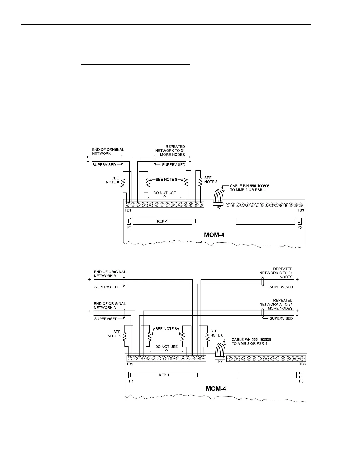
REP-1 Connections and Ratings
Electrical connections:
A basic repeater connects to the net-
work at the end of the run. A repeater
can extend the distance of the network
or can add more nodes to the system.
If a basic repeater is in place, the
original network ends at the REP-1 and
is terminated with a 120 ohm resistor.
Basic Repeater - Style 7 Wiring
The new repeated network begins at
the REP-1 and also has an end of line
resistor. In a Style 4 network the
second half of the REP-1 is not used,
so it has both sides terminated. For
Style 7 networks use both halves of
the REP-1. For additional wiring infor-
mation see the REP-1 Installation
Instructions, P/N 315-092686.
NOTES
1. Power limited to
NFPA 70 per NEC 760.
2. Minimum wire size:
18 AWG.
3. Maximum resistance:
80 ohms per pair.
4. Use twisted pair or
shielded twisted pair
5. Terminate the shield
ONLY at the MMB-1/2
enclosure.
6. Maximum voltage:
8V P-P.
7. Maximum current:
150mA.
8. Use the end of line
resistor:
P/N 140-820150
(120 ohms, ¼W).
Basic Repeater - Style 4 Wiring
NOTES
1. Power limited to
NFPA 70 per NEC 760.
2. Minimum wire size:
18 AWG.
3. Maximum resistance:
80 ohms per pair.
4. Use twisted pair or
shielded twisted pair
5. Terminate the shield
ONLY at the MMB-1/2
enclosure.
6. Maximum voltage:
8V P-P.
7. Maximum current:
150mA.
8. Use the end of line
resistor:
P/N 140-820150
(120 ohms, ¼W).
Technical Manuals Online! - http://www.tech-man.com

 Loading...


