4 - 108
TBM-2 Connections and Ratings
The other audio risers connect in a
similar fashion.
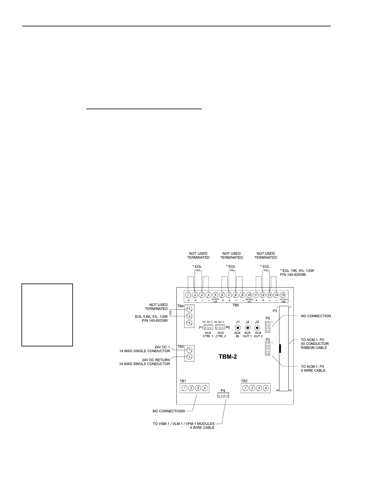
Style Y connections
Use only one cable.
Connect the riser cables to TB5 in the
desired style, using 18-14 AWG
twisted, shielded pair. The other ends
of the risers connect to the OCC-1
terminal block. Refer to the OCC-1
Installation Instructions, P/N 315-
090918, for further details.
For connections to other connectors
and terminal blocks, refer to the appro-
priate module installation instructions.
TBM-2 Wiring in an Expander Enclosure
NOTES
1. All wiring must be in
accordance with
Article 760 of NEC or
the local building
codes.
WARNING
The user must comply
with AUX IN and AUX
OUT specifications or
the MXLV System may
not function properly.
Always complete the
full system test to
ensure that all
applications function
completely.
All wiring must be in accordance with
Article 760 of NEC or the local building
codes.
Electrical connections:
Connect the 24 VDC to TB3 using 14 AWG
single conductor wire. Terminal 1 is for
+24 VDC; terminal 2 is for 24 VDC return.
Refer to the CSG-M configuration
printout to determine the wiring style,
either Class B (Style Y) or Class A
(Style Z) for terminal block TB5.
For Style Z wiring
Connect terminals 1 and 4 in one cable
going out to Riser 1.
Connect terminals 2 and 3 in another
cable coming back from the last
destination of Riser 1.
Technical Manuals Online! - http://www.tech-man.com

 Loading...


