2 - 19
Installation
Setting the Module Addresses
Remove the module from its protec-
tive bag.
Refer to the CSG-M configuration
printout for the address of the
module.
Set the module address on switch
S9 for a VSM-1 or a VLM-1, using
switches SW1-SW6. For the VFM-1,
use switch S5.
After setting the address of each
module, label each switch or LED.
When viewed from the front panel
of the VSM-1/VLM-1/VFM-1, the
labels are on the left and the
switches and LEDs are on the right.
Remove the label strip from its slot
and type or print a brief function
identifier for each switch.
After completing the label strip,
insert it back into its slot.
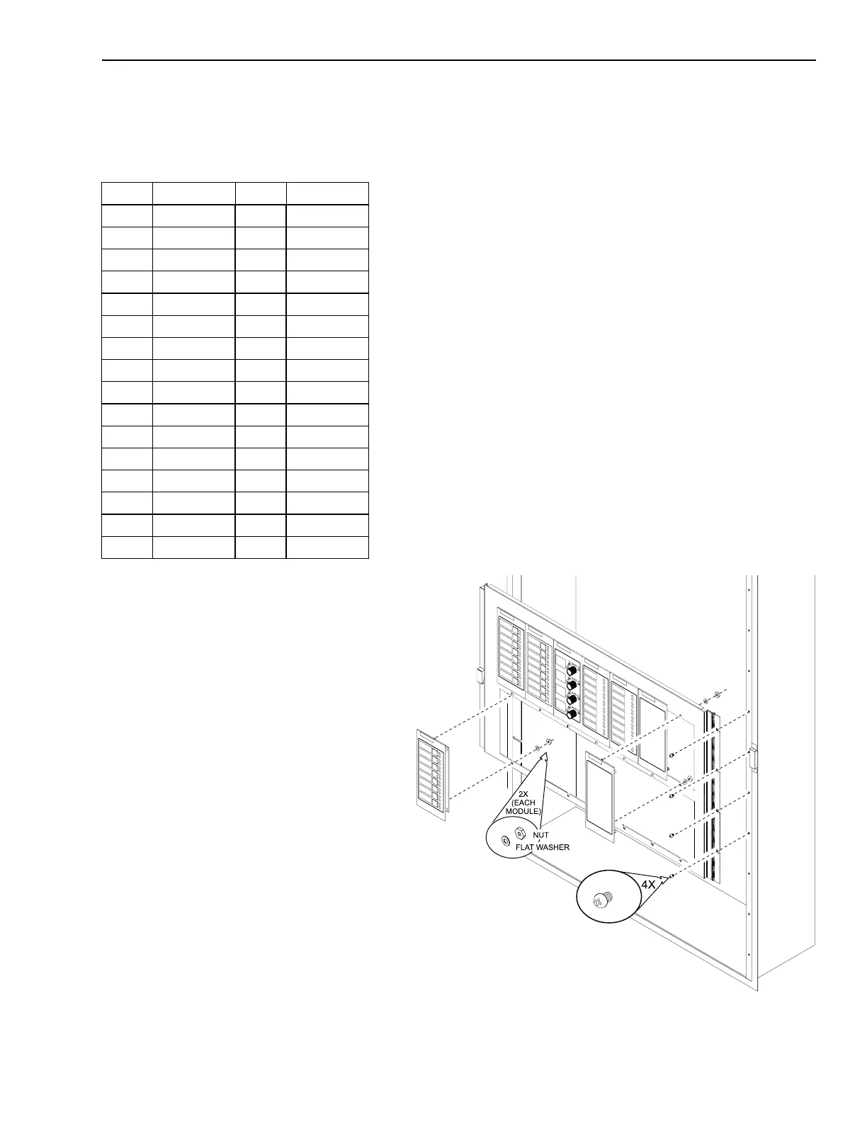
Installing VSM-1 / VLM-1 / VFM-1 / VSB-1
Mounting the VSM/VLM/VFM/VSB
Before mounting each VSM-1/VLM-1/
VFM-1 module, check the labels and
the address setting of S9 or S5 on the
back of the module.
Mount the VSM-1/VLM-1 modules in
the Model MDH-3/-4/-5 panel, starting
at the left-hand corner directly below
the microphone. This position is
recommended for important assigned
functions, such as ALL CALL.
Group the modules together by func-
tion or by some logical order. VSM-1/
VLM-1/VFM-1 modules do not need to
be mounted in numeric order by
address.
VSM-1/VLM-1/VFM-1 SWITCH SETTINGS
Address 6 5 4 3 2 1 Address 6 5 4 3 2 1
Illegal O O O O O O 16 O X O O O O
1 O O O O O X 17 O X O O O X
2 O O O O X O 18 O X O O X O
3 O O O O X X 19 O X O O X X
4 O O O X O O 20 O X O X O O
5 O O O X O X 21 O X O X O X
6 O O O X X O 22 O X O X X O
7 O O O X X X 23 O X O X X X
8 O O X O O O 24 O X X O O O
9 O O X O O X 25 O X X O O X
10 O O X O X O 26 O X X O X O
11 O O X O X X 27 O X X O X X
12 O O X X O O 28 O X X X O O
13 O O X X O X 29 O X X X O X
14 O O X X X O 30 O X X X X O
15 O O X X X X 31 O X X X X X
X=Closed or ON O=Open or OFF
Technical Manuals Online! - http://www.tech-man.com

 Loading...


