3 Functions Issue 10/06
MICROMASTER 440 Operating Instructions
138 6SE6400-5AW00-0BP0
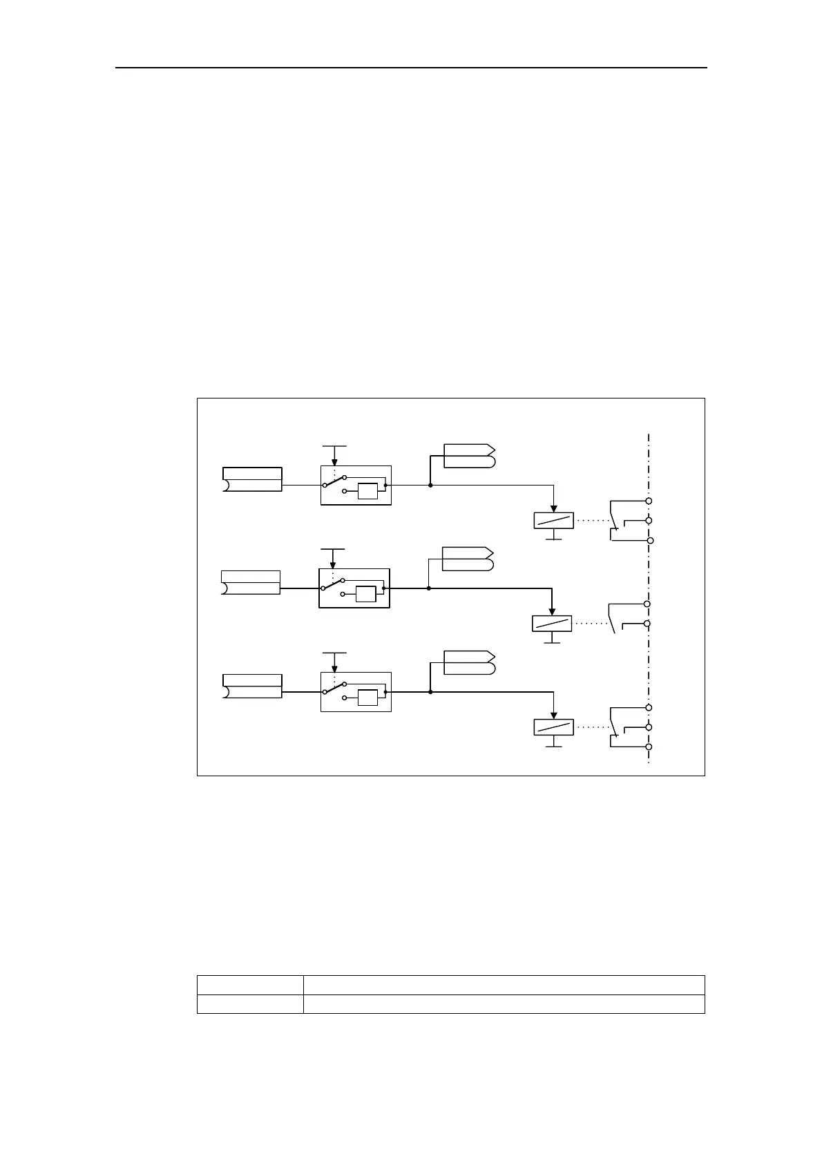
3.6.2 Digital outputs (DOUT)
Number: 3
Parameter range: r0730 – P0748
Function chart number: FP2100
Features:
- cycle time: 1 ms
Binary states in the drive can be output via the digital outputs. As result of the fast
cycle time, it is possible to control external devices and to display the state in real
time. In order that higher powers can also be output, the internal signal (TTL level)
is amplified using a relay (refer to Fig. 3-30).
Relay:
- max. opening / closing time: 5 / 10 ms
- voltage / current 30 V DC / 5 A
250 V AC / 2 A
(52:3)
I: Fct. of DOUT 1
P0731.C
-1
0
1
Invert DOUTs
0 ... 7
P0748 (0)
CO/BO: State DOUTs
r0747
r0747
NO
COM
NC
Kl.20
Kl.19
Kl.18
(52:7)
I: Fct. of DOUT 2
P0732.C
-1
0
2
Invert DOUTs
0 ... 7
P0748 (0)
CO/BO: State DOUTs
r0747
r0747
NO
COM
Kl.22
Kl.21
(0:0)
I: Fct. of DOUT 3
P0733.C
-1
0
4
Invert DOUTs
0 ... 7
P0748 (0)
CO/BO: State DOUTs
r0747
r0747
NO
COM
NC
Kl.25
Kl.24
Kl.23
.0
.1
.2
Fig. 3-30 Digital outputs
The states, which are to be output, are defined using the "BI" parameters P0731
(digital output 1), P0732 (digital output 2) and P0733 (digital output 3). For the
definition, the "BO" parameter number or "CO/BO" parameter number and the bit
number of the particular state should be entered into P0731 – P0733. Frequently
used states including the parameter number and bit are shown in the following
Table (refer to Table 3-12).
Table 3-12 Parameters P0731 – P0733 (frequently used functions / states)
Parameter value Significance
52.0 Drive ready

 Loading...


