3 Functions Issue 10/06
MICROMASTER 440 Operating Instructions
56 6SE6400-5AW00-0BP0
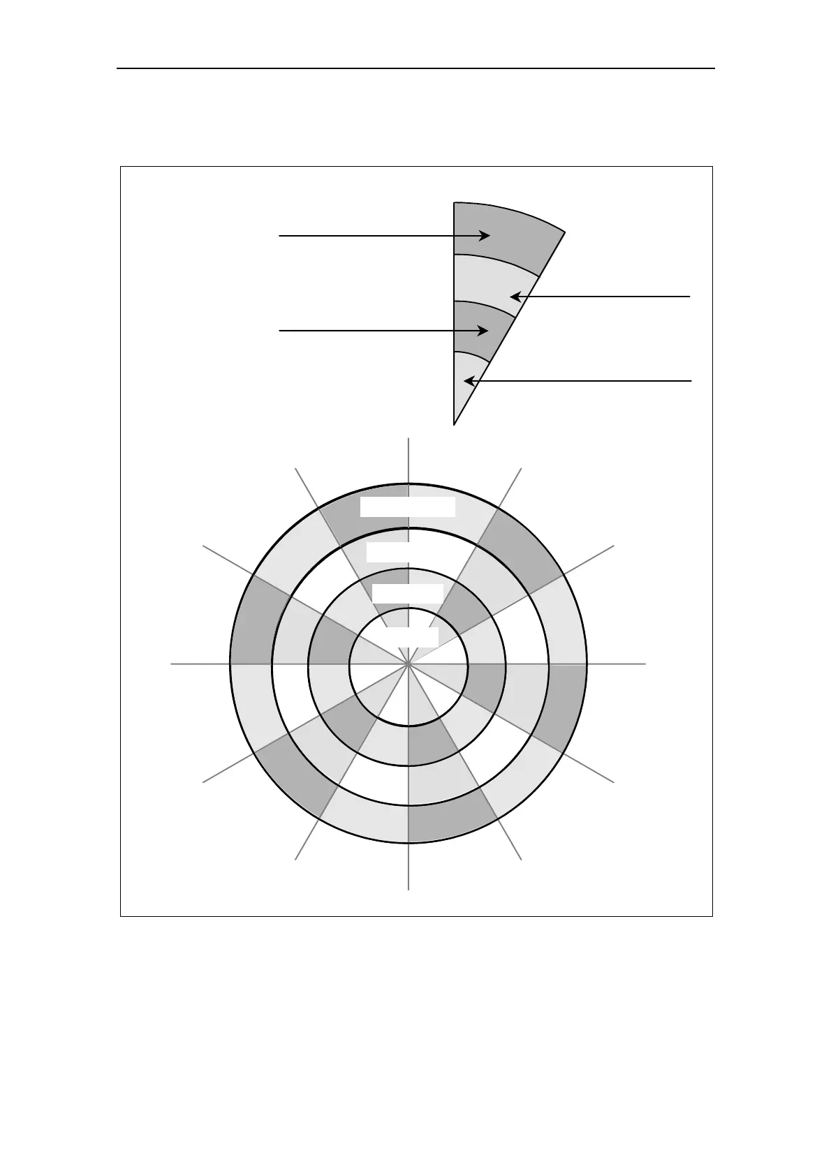
The interrelationship between access level P0003 and the grouping P0004 is
schematically shown in Fig. 3-3.
P0004 = 2
P0004 = 3
P0004 = 7
P0004 = 8
P0004 = 10
P0004 = 12
P0004 = 13
P0004 = 20
P0004 = 21
P0004 = 22
P0004 = 0
P0004 = 2
P0004 = 2, P0003 = 1
P0004 = 2, P0003 = 2
P0004 = 2, P0003 = 4
P0004 = 2, P0003 = 3
(no filter function)
allows direct access
to the parameters.
For BOP and AOP
depending on the
selected access level
Parameters level 1
concerning the inverter unit
Parameters level 1, 2 and 3
concerning the inverter unit
Inverter Unit
Parameters level 1 and 2
concerning the inverter unit
Parameters level 1, 2, 3 and 4
concerning the inverter unit
Inverter Unit
Motor Data
PID Controller
Alarms, Warnings &
Monitoring
Motor Control
P1300 ... P1799
Drive Features
P1200 ... P1299
Setpoint Channel &
Ramp Generator
P1000 ... P1199
Speed sensor
P0400 ... P0499
Commands and
Digital I/O
P0700 ... P0749
P0800 ... P0899
Communication
P2000 ... P2099
P0004 = 5
P0004 = 4
Technology
Application / units
P0400 ... P0499
Analogue I/O
P0750 ... P0799
P0200 ... P0299
P0300 ... P0399
P0600 ... P0699
P0003 = 1
P0003 = 2
P0003 = 3
P0003 = 4
P0003 = 1
2
3
4
Standard
Extended
Expert
Service
User access level
Fig. 3-3 Parameter grouping / access
 Loading...


