2 Installation Issue 10/06
MICROMASTER 440 Operating Instructions
32 6SE6400-5AW00-0BP0
2.3.2 Installing communication options and/or pulse encoder
evaluation module
Sizes A to F
NOTE
When installing the following options – PROFIBUS module, DeviceNet module,
CANopen option module and/or pulses encoder evaluation module, the mounting
depth of the drive inverter is increased!
Please refer to the relevant Operating Instructions for the actual procedure.
Sizes FX and GX
The front cover of the MICROMASTER 440 is designed so that the control module
(normally the SDP) is almost flush with the opening in the front cover.
If more than one option is to be installed in the electronic box, it is necessary to
position the entire electronic box further to the rear
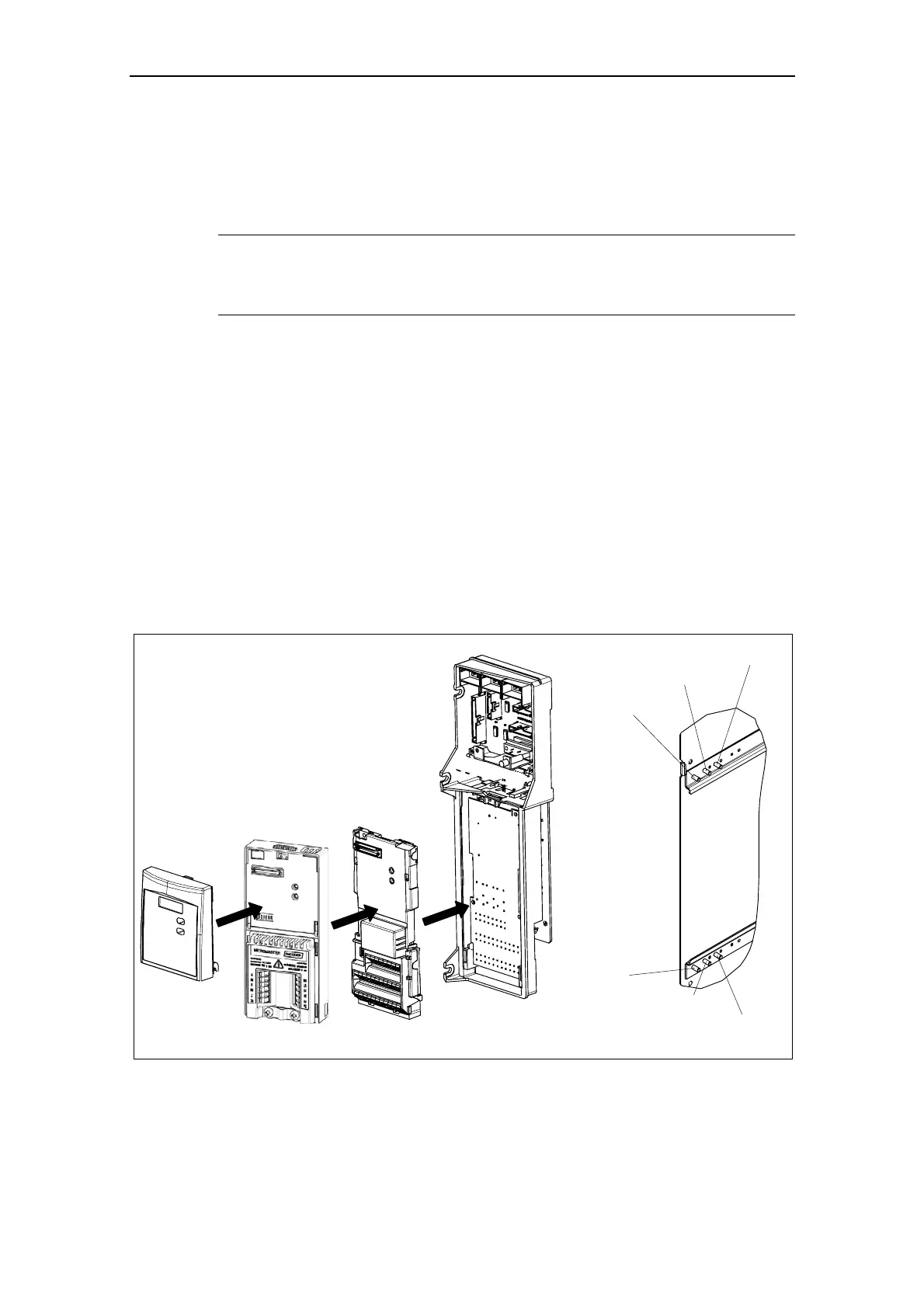
Installing the options
¾ Remove the front cover:
• Unscrew two screws at the bottom side of the front cover.
• Lift front cover up and out.
¾ Remove retaining screws on the electronic box.
¾ Screw on electronic box in correct installation position as shown in Fig. 2-7
¾ Install additional options.
¾ Reinstall front cover.
Installation position 2
Installation position 2
Installation position 1
Installation position 1
Standard installation
Standard installation
Fig. 2-7 Options for the electronic box
 Loading...


