Issue 10/06 3 Functions
MICROMASTER 440 Operating Instructions
6SE6400-5AW00-0BP0
155
NOTE
If a higher baud rate or higher number of nodes is required, then the CB option
boards (e.g. PROFIBUS, CAN) should be used to ensure disturbance-free
operation.
3.7.1.2 The structure of net data
Information which, for example, a SIMATIC S7 control unit (= master) sends to a
drive (= slave) or the drive sends to the control unit is placed in the net-data area of
each telegram.
General structure of the net-data block
The net-data block is divided into two areas:
¾ the PKW (parameter ID value) range
¾ the PZD (process data) range
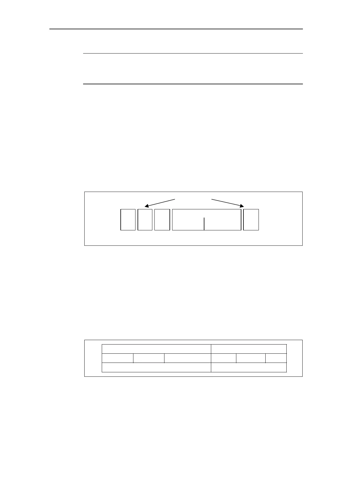
The structure of the net data in the USS-protocol telegram is shown below.
Protocol frame
Parameter ID value
(parameter area)
STX LGE ADR
(PKW) (PZD)
BCC
PKW: PZD:
Process data
(process-data area)
Process dataParameter
Net data
Fig. 3-45 Telegram structure
¾ The PKW area relates to the handling of the parameter ID value (PKW)
interface. The PKW interface is not a physical interface but a mechanism which
handles parameter transfer between two communication partners (e.g. control
unit and drive). This involves, for example, reading and writing parameter
values and reading parameter descriptions and associated texts.
All tasks which are performed via the PKW interface essentially involve operator
control and visualization, service and diagnosis.
¾ The PZD area contains the signals required for the automation system:
♦ Control word(s) and setpoint(s) from the master to the slave
♦ Status word(s) and actual value(s) from the slave to the master.
PKW area
PKE IND PZD1 • • • PZD16
PZD area
PKW elements
variable length variable length
Fig. 3-46 Structure of the PKW and PZD areas
The two areas together make up the net data block. This structure applies to
telegrams from the master to the slave and vice versa.