Issue 10/06 3 Functions
MICROMASTER 440 Operating Instructions
6SE6400-5AW00-0BP0
61
As can be seen from the examples above, connector parameters have the
following abbreviations in front of the parameter names:
¾
CI Connector Input, signal sink ("P" parameters)
→ The CI parameter can be interconnected with a connector output as source,
by entering the parameter number of the connector output (CO parameter)
as value in the CI parameter (e.g.: P0771 = 21).
¾
CO Connector Output, signal source ("r" parameters)
→ The CO parameter can be used as source for CI parameters. For the
particular interconnection, the CO parameter number must be entered in the
CI parameter (e.g.: P0771 = 21).
Further, MICROMASTER has "r" parameters where several binector outputs are
combined in a word (e.g.: r0052 CO/BO: Status word 1). This feature reduces, on
one hand, the number of parameters and simplifies parameterization via the serial
interface (data transfer). This parameter is further characterized by the fact that it
does not have any units and each bit represents a digital (binary) signal.
As can be seen from the examples of parameters, these combined parameters
have the following abbreviation in front of the parameter names:
¾
CO/BO Connector Output / Binector Output, signal source ("r"
parameters)
→ CO/BO parameters can be used as source for CI parameters and BI
parameters:
a) In order to interconnect all of the CO/BO parameters, the parameter
number must be entered into the appropriate CI parameter (e.g.:
P2016[0] = 52).
b) When interconnecting a single digital signal, in addition to the CO/BO
parameter number, the bit number must also be entered into the BI
parameter (e.g.: P0731 = 52.3)
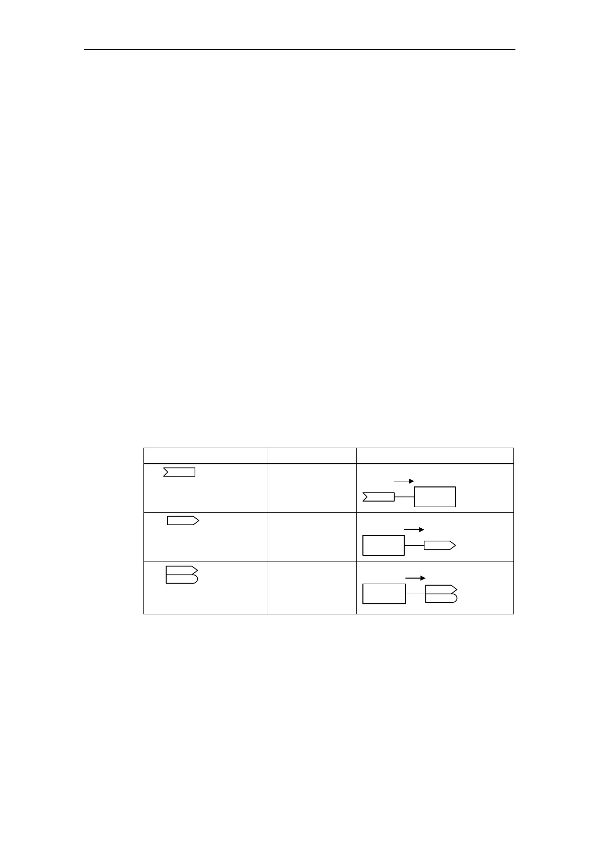
Abbreviation and symbol Name Function
CI
Connector input
(signal receiver)
Data flow
Pxxxx
CI: ...
Function
CO
Connector output
(signal source)
Data flow
Function
rxxxx
CO: ...
CO
BO
Binector/connector
output
(signal source)
Data flow
Functions
rxxxx
CO/BO: ...
Fig. 3-5 Connectors
In order to interconnect two signals, a BICO setting parameter (signal receiver)
must be assigned the required BICO monitoring parameter (signal source). A
typical BICO interconnection is shown using the following examples (refer to Fig.
3-6).

 Loading...


