2 Installation Issue 10/06
MICROMASTER 440 Operating Instructions
24 6SE6400-5AW00-0BP0
2.2 Ambient operating conditions
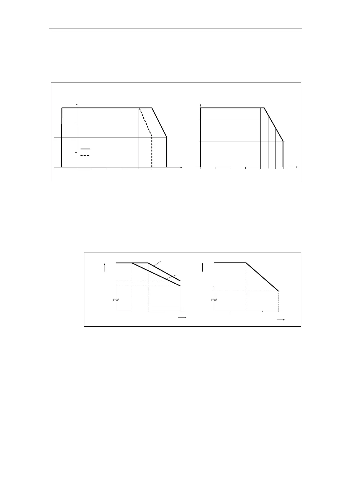
Temperature
Frame Sizes A to F: Frame Sizes FX and GX:
0203010 40
[°C]
Ambient temperature
50 55
95
100
[%]
Permissible output current
90
85
45
0
20 30
10
40
[°C]
Ambient temperature
-10
50
60
constant torque
variable torque
75
50
25
100
[%]
Permissible output current
Fig. 2-2 Ambient operating temperature
Humidity Range
Relative air humidity ≤ 95 % Non-condensing
Altitude
If the inverter is to be installed at an altitude > 1000 m or > 2000 m above sea
level, derating will be required:
Permissible output current
Installation altitude in m above sea level
Permissible input voltage
80
100
01000
2000
3000 4000
%
Installation altitude in m above sea level
77
85
100
01000
2000
3000 4000
%
80
Frame Sizes
FX and GX
Frame Sizes
A to F
Fig. 2-3 Installation altitude
Shock and Vibration
Do not drop the inverter or expose to sudden shock. Do not install the inverter in an
area where it is likely to be exposed to constant vibration.
Mechanical strength to EN 60721-33
¾ Deflection: 0.075 mm (10 ... 58 Hz)
¾ Acceleration: 9.8 m/s
2
(> 58 ... 200 Hz)
Electromagnetic Radiation
Do not install the inverter near sources of electromagnetic radiation.