3 Functions Issue 10/06
MICROMASTER 440 Operating Instructions
248 6SE6400-5AW00-0BP0
3.23.2.3 Speed controller
Parameter range: P1300, P1400 – P1780
SLVC: P1470, P1472, P1452
VC: P1460, P1462, P1442
Warnings -
Faults -
Function chart number: FP7500, FP7510
Both of the control techniques (SLVC, VC) have the same speed controller
structure which includes the following components as kernel:
¾ PI controller
¾ Speed controller pre-control
¾ Droop
The sum of the output quantities forms the speed setpoint, which is reduced to the
permissible level using the torque setpoint limiting function (refer to Section
3.23.2.4).
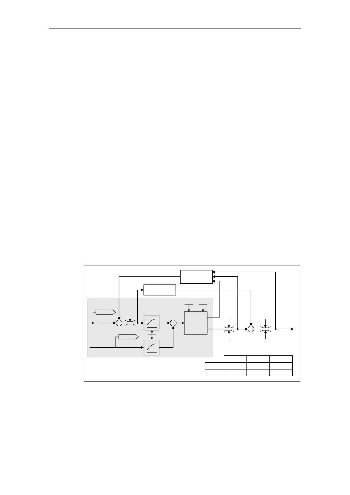
Speed controller (SLVC: P1470, P1472, P1452 VC: P1460, P1462, P1442)
The speed controller (refer to Fig. 3-105) receives its setpoint r0062 from the
setpoint channel (refer to Section 3.12), the actual value r0063 either directly from
the speed actual value encoder or, for VC, also directly through the motor model
for SLVC. The system error is amplified by the PI controller and, together with the
pre-control, forms the torque setpoint.
For increasing load torques, when the droop function is active, the speed setpoint
is proportionally reduced so that the load on an individual drive within a group
(where two or several motors are mechanically coupled) is reduced when
excessively high torques occur.
–
Torque
setpoint
Droop
Act. frequency
–
r1538 r1538
r1539 r1539
Pre-
control
Freq. setpoint
PI
Speed
controller
SLVC:
VC:
P1452
P1442
P1470
P1460
P1472
P1462
T
i
K
p
T
n
T
i
K
p
T
n
r1084
r0063
r0062
Speed control
*)
*) only active if pre-control is activated
(P1496 > 0)
Fig. 3-105 Speed controller

 Loading...


