Issue 10/06 3 Functions
MICROMASTER 440 Operating Instructions
6SE6400-5AW00-0BP0
191
3.13 Free function blocks (FFB)
Parameter range: P2800 – P2890
Warnings -
Faults -
Function chart number: FP4800 – FP4830
Cycle time: 128 ms
For many applications, interlocking logic is required in order to control (open-loop)
the drive inverter. This interlocking logic couples several states (e.g. access
control, plant/system state) to form a control signal (e.g. ON command). Previously
this was implemented using either a PLC or relays. This represented additional
costs for the plant or system. In addition to logic operations, increasingly, arithmetic
operations and storage elements are required in drive inverters which generate a
new unit from several physical quantities. This simplified PLC functionality is
integrated in MICROMASTER 440 using the freely programmable function blocks
(FFB).
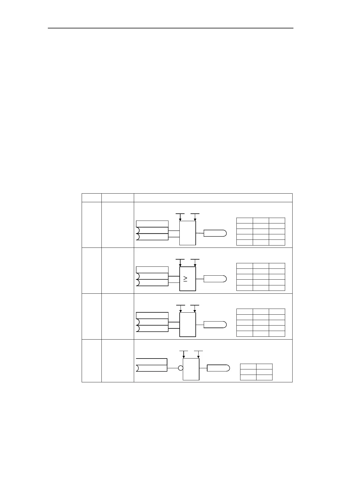
The following function blocks are integrated in MICROMASTER 440:
Table 3-31 Free function blocks
No. Type Example
3 AND AND 1
P2800
P2801[0]
A
B
C
&
P2810
r2811
ABC
000
010
100
111
Index0
Index1
3 OR OR 1
A
B
C
P2816
r2817
ABC
000
011
101
111
1
P2800
P2801[3]
Index0
Index1
3 XOR XOR 1
A
B
C
P2822
r2823
ABC
000
011
101
110
1
=
P2800
P2801[6]
Index0
Index1
3 NOT NOT 1
P2828
r2829
1
CA
AC
01
10
P2800
P2801[9]
Index0