Issue 10/06 3 Functions
MICROMASTER 440 Operating Instructions
6SE6400-5AW00-0BP0
99
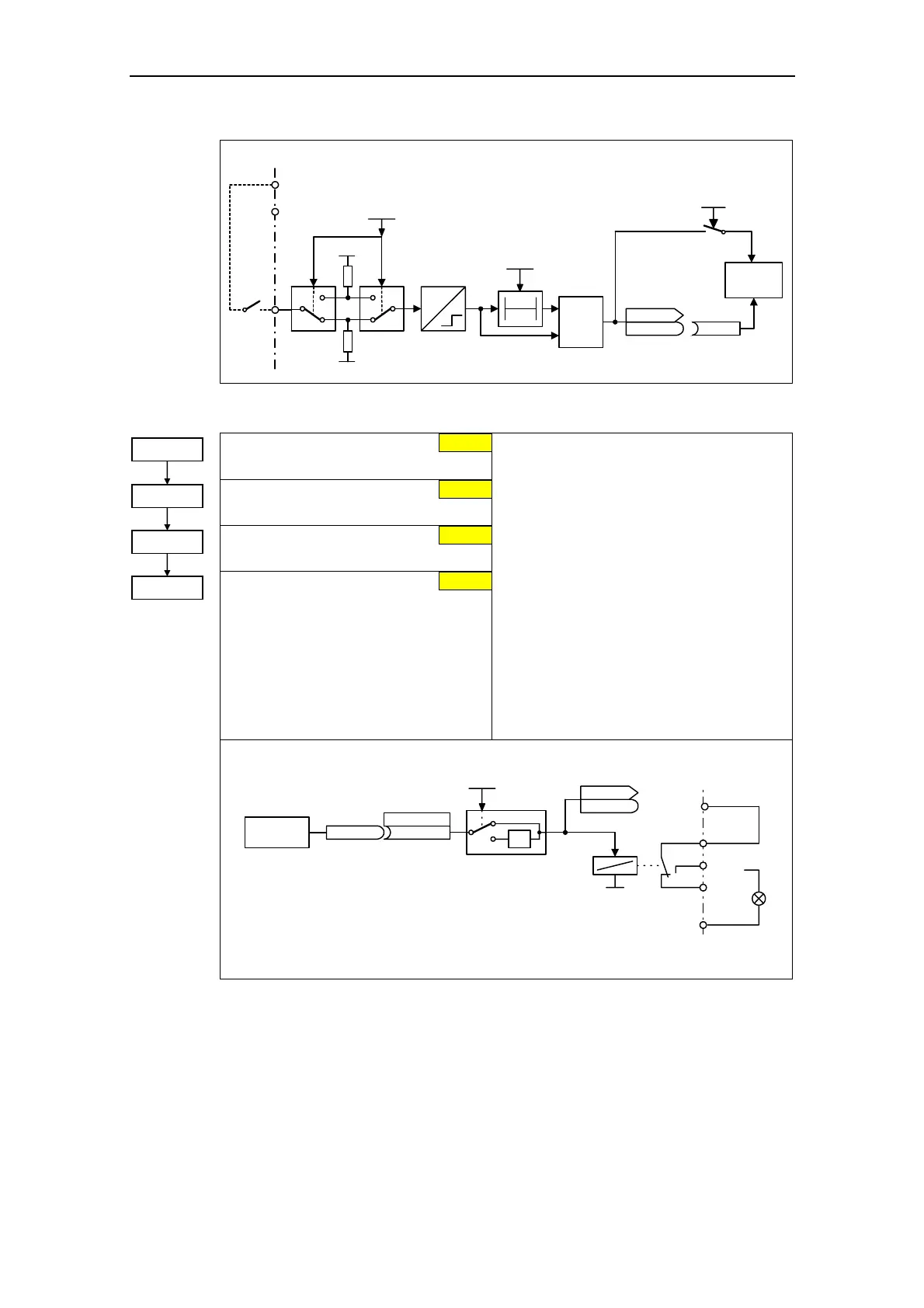
DIN channel (e.g. DIN1 - PNP (P0725 = 1))
24 V
T0
&
0
1
PNP/NPN DIN
0 ... 1
P0725 (1)
0 V
24 V
Debounce time: DIN
0 ... 3
P0724 (3)
CO/BO: Bin.inp.val
r0722
r0722
.0
Kl.9
P24 (PNP)
Kl.28
0 V (NPN)
Pxxxx BI: ...
P0701
Function
0
1
3.5.7.4 Digital output (DOUT)
BI: Function of digital output 1 *
Defines source of digital output 1.
BI: Function of digital output 2 *
Defines source of digital output 2.
BI: Function of digital output 3 *
Defines source of digital output 3.
Invert digital output
Defines high and low states of relay for a
given function.
Common Settings:
52.0 Drive ready 0
52.1 Drive ready to run 0
52.2 Drive running 0
52.3 Drive fault active 0
52.4 OFF2 active 1
52.5 OFF3 active 1
52.6 Switch on inhibit active 0
52.7 Drive warning active 0
52.8 Deviation, setpoint / actual value 1
52.9 Control from PLC (PZD control) 0
52.A Maximum frequency reached 0
52.B Alarm: Motor current limiting 1
52.C Motor holding brake (MHB) active 0
52.D Motor overload 1
52.E Motor direction of rotation, clockwise 0
52.F Frequency inverter overload 1
53.0 DC brake active 0
.
(52:3)
BI: Fct. of DOUT 1
P0731.C
-1
0
1
Invert DOUTs
0 ... 7
P0748 (0)
CO/BO: State DOUTs
r0747
r0747
Kl.20
Kl.18
.0
Function
xxxx.y
rxxxx.y
P0731 = xxxx.y
DOUT channel
Relay :
DC 30 V / 5 A
AC 250 V / 2 A
Kl.28
Kl.9
int. 24 V
max. 100 mA
NO
COM
NC
Kl.19
or
Text
max. opening / closing time
5 / 10 ms
52.3
0
P0731 = ...
52.7
0.0
P0748 = ...
P0733 = ...
P0732 = ...