2 Installation Issue 10/06
MICROMASTER 440 Operating Instructions
38 6SE6400-5AW00-0BP0
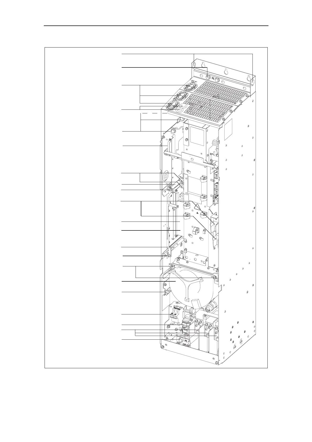
Shield connection
Mains cable PE
Hoisting eyes
Mains cable
Phase U1/L1, V1/L2, W1/L3
Top adjustment rail
Bottom adjustment rail
Status Display Panel
Shield connection
control leads
Transformer adaption
Motor cable
Phase U2, V2, W2
Motor cable
PE Shield connection
Fan screws
Bottom retaining screw
Elektronic box
Top retaining screw
Connection to
Y-Capacitor
Fan fuses
Cable opening for
mains conection
U1/L1, V1/L2, W1/L3
Fan
Cable opening DCPA, DCNA
for connection of an
external braking unit
Connection DCPA, DCNA
for external braking unit
Connection for dv/dt filter
DCPS, DCNS
Fig. 2-9 MICROMASTER 440 connection drawing – frame size FX