3 Functions Issue 10/06
MICROMASTER 440 Operating Instructions
164 6SE6400-5AW00-0BP0
3.7.1.3 USS bus configuration via COM link (RS485)
In order to ensure disturbance-free USS operation, the bus cable must be
terminated at both ends using bus terminating resistors. In this case, the bus cable
from
the first USS device [node] up to the last USS device [node] should be
considered as one
bus cable – so that the USS bus should be terminated twice.
For the
first bus node [device] (e.g. master) and last bus node [device] (e.g. drive
converter), th bus terminating resistor must be switched-in.
NOTE
♦ When supplied, the bus terminating resistors are not switched-in!
♦ Please note that you only switch-in the bus terminating at the first bus node
[device] and last bus note [device]! The
bus terminating resistors should be
always set with the system in a
no-voltage state (e.g. powered-down)!
♦ Data transfer errors on the bus are possible!
In active bus operation, devices where the terminating
resistor is switched-in,
may not be in a no-voltage state. The terminating resistor draws the voltage
from the connected device. This is the reason that the terminating resistor is no
longer effective when the device is in a no-voltage state (e.g. when powered
down) .
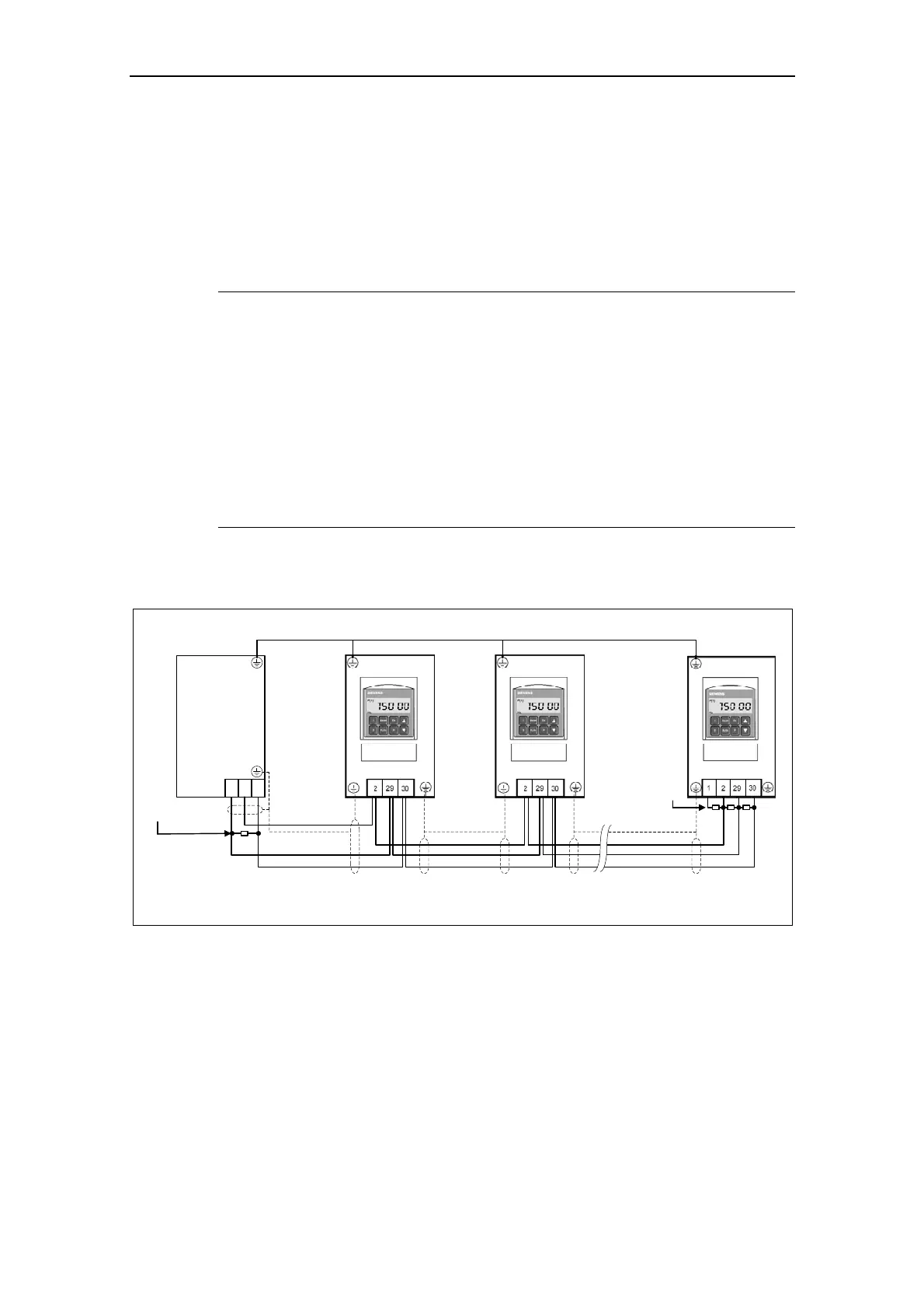
The following diagram shows the structure of a bus connection through terminals
29, 30:
Screening
Screening Screening
Potential equilization cable
RS485 terminator
RS485 terminator
Master
0 V
(M)
− a terminating resistor must be connected at the first and last devices [nodes] on the bus cable
− no bus termination for other devices [nodes]
Fig. 3-47 Connecting the USS bus cable

 Loading...


