Issue 10/06 3 Functions
MICROMASTER 440 Operating Instructions
6SE6400-5AW00-0BP0
247
3.23.2.2 Vector control with speed encoder (VC)
Parameter range: P1400 – P1740
P0400 – P0494
Warnings -
Faults -
Function chart number: FP7000
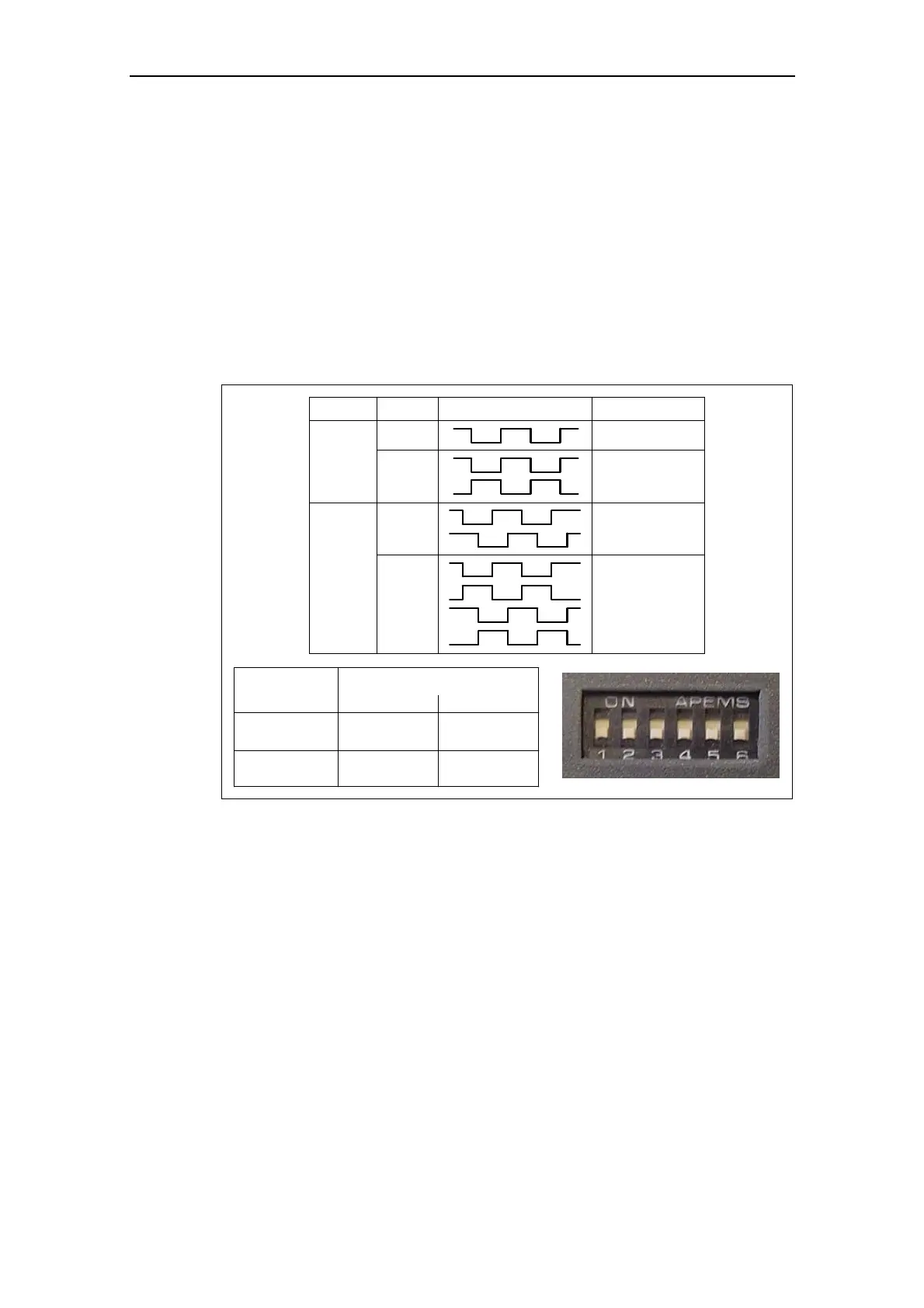
For Vector control with speed encoder (refer to Table 3-40), a pulse encoder
evaluation (option module) as well as a pulse encoder, e.g. encoder with 1024
pulses/revolution are required. In addition to the correct wiring, the pulse encoder
module must be activated, corresponding to the encoder type, using the parameter
range P0400 – P0494 or using the DIP switch on the module (refer to Fig. 3-104).
Parameter
Terminal Track Encoder output
single ended
P0400 = 1 A
differential
A
AN
A
B
A
AN
B
BN
differential
P0400 = 2
single ended
Output
Type
differential
TTL
(e.g. 1XP8001-2)
HTL
111111 010101
(e.g. 1XP8001-1)
101010 000000
single ended
Fig. 3-104 P0400 and DIP switch on the pulse encoder module
Advantages of Vector control with encoder:
¾ The speed can be closed-loop controlled down to 0 Hz (i.e. at standstill)
¾ Stable control behavior over the complete speed range
¾ Constant torque in the rated speed range
¾ When compared to closed-loop speed control without encoder, the dynamic
response for drives with encoder is significantly higher as the speed is directly
measured and is incorporated in generating the model of current components i
d
,
i
q
.

 Loading...


