3 Functions Issue 10/06
MICROMASTER 440 Operating Instructions
60 6SE6400-5AW00-0BP0
3.1.2.3 BICO technology
Using BICO technology (English: Binector Connector Technology), process data
can be freely interconnected using the "standard" drive parameterization. In this
case, all values which can be freely interconnected (e.g. frequency setpoint,
frequency actual value, current actual value, etc.) can be defined as "Connectors"
and all digital signals which can be freely interconnected (e.g. status of a digital
input, ON/OFF, message function when a limit is violated etc.) can be defined as
"Binectors".
There are many input and output quantities as well as quantities within the closed-
loop control which can be interconnected in a drive unit. It is possible to adapt the
drive to the various requirements using BICO technology.
A binector is a digital (binary) signal without any units and which can either have
the value 0 or 1. Binectors always refer to functions whereby they are sub-divided
into binector inputs and binector outputs (refer to Fig. 3-4). In this case, the
binector input is always designated using a "P" parameter with attribute "BI" (e.g.:
P0731 BI: Function, digital output 1), while the binector output is always
represented using an "r" parameter with attribute "BO" (e.g.: r0751 BO: ADC status
word).
As can be seen from the examples above, the binector parameters have the
following abbreviations in front of the parameter names:
¾
BI Binector Input, signal receiver ("P" parameters)
→ The BI parameter can be interconnected with a binector output as source, by
entering the parameter number of the binector output (BO parameter) as
value in the BI parameter (e.g.: Interconnecting the "BO" parameter r0751
with "BI" parameter P0731 → P0731 = 751).
¾
BO Binector Output, signal source ("r" parameters)
→ The BO parameter can be used as source for BI parameters. For the
particular interconnection the BO parameter number must be entered into
the BI parameter (e.g.: Interconnecting the "BO" parameter r0751 with "BI"
parameter P0731 → P0731 = 751).
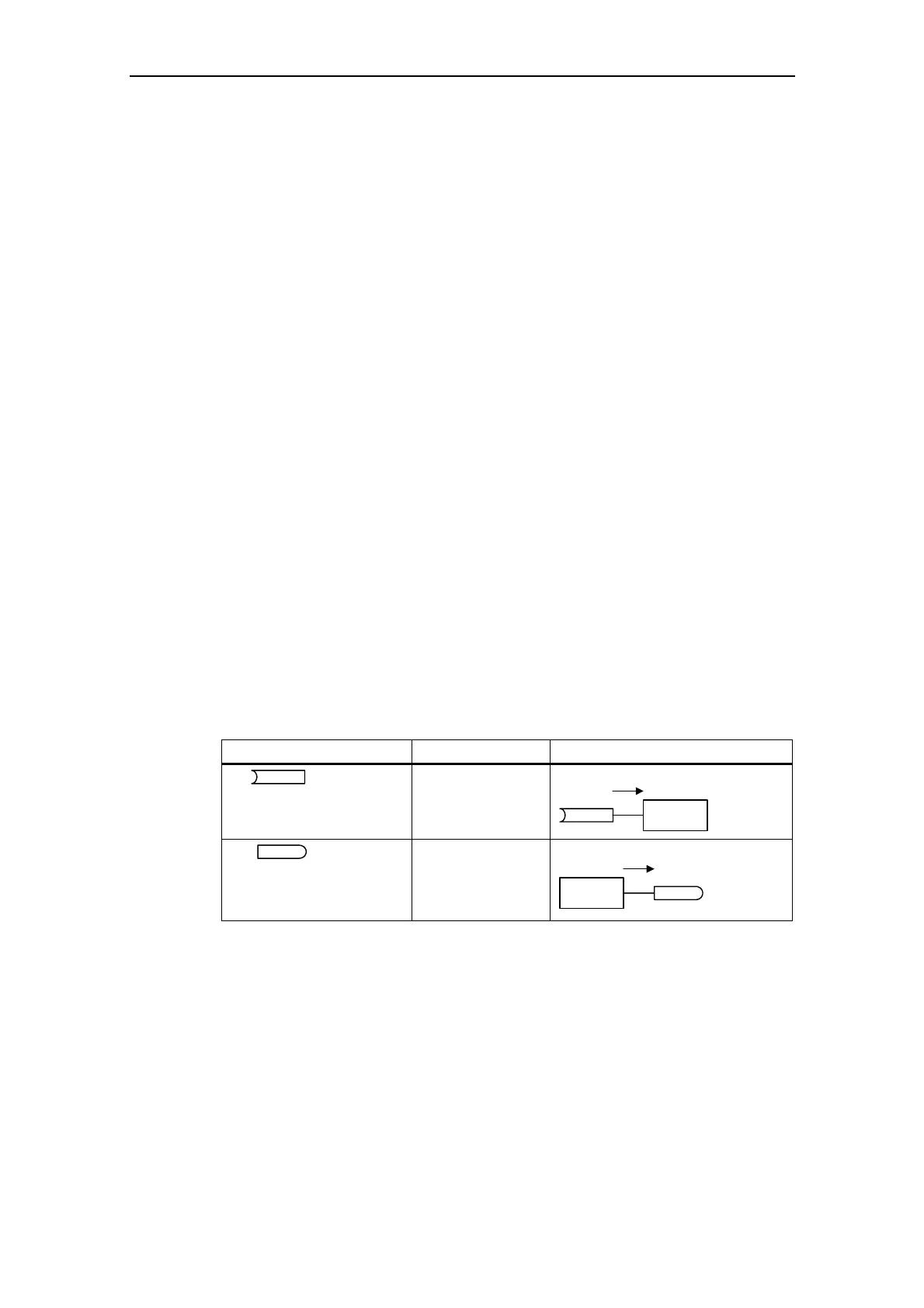
Abbreviation and symbol Name Function
BI
Binector input
(signal receiver)
Data flow
Pxxxx
BI: ...
Function
BO
Binector output
(signal source)
Data flow
Function
rxxxx
BO: ...
Fig. 3-4 Binectors
A connector is a value (16 or 32 bit), which can include a normalized quantity
(without dimension) as well as also a quantity with associated units. Connectors
always refer to functions whereby they are sub-divided into connector inputs and
connector outputs (refer to Fig. 3-5). Essentially the same as the binectors, the
connector inputs are characterized by a "P" parameter with attribute "CI" (e.g.:
P0771 CI: D/A converter); while the connector outputs are always represented
using an "r" parameter with attribute "CO" (e.g.: r0021 CO: Smoothed output
frequency).