3 Functions Issue 10/06
MICROMASTER 440 Operating Instructions
182 6SE6400-5AW00-0BP0
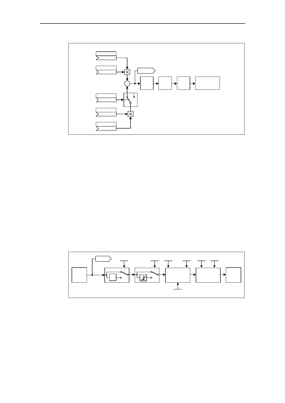
AFM Limit RFG
r1078
01
CI: Add. setp.scal
(1:0)
P1076.C
CI: Add. setpoint
(0:0)
P1075.C
(0:0)
BI: Disab.add.setp
P1074.C
CI: Main setp scal
(1:0)
P1071.C
CI: Main setpoint
(755:0)
P1070.C
+
+
Motor
control
Fig. 3-60 Summation
MICROMASTER has the following possibilities to select the setpoint source:
1. P1000 – selecting the frequency setpoint source
2. P0719 – selecting the command / setpoint source
3. BICO parameterization
- P1070 CI: Main setpoint
- P1075 CI: Additional setpoint
Further, the main setpoint as well as the supplementary (additional) setpoint can be
scaled independently of one another. In this case, for example, a user can simply
implement an override function using the appropriate parameterization.
A scan sequence is generally associated with a forwards and a backwards motion.
When selecting the reversing functionality, after reaching the end position, a
direction of rotation reversal can be initiated in the setpoint channel (refer to Fig.
3-61).
On the other hand, if it is to be prevented that a direction of rotation reversal or a
negative frequency setpoint is to be entered via the setpoint channel, then this can
be inhibited using BICO parameter P1110.
SUM
-1
0
1
0
1
P1113
r1078
P1110 P1091 P1094
P1101
...
Skip Limit
P1080 P1082
RFG
Fig. 3-61 Modifying the frequency setpoint
Driven machines can have one or several resonance points in the range from 0 Hz
up to the reference frequency. These resonance points result in oscillations which,
under worst case conditions, can damage the driven load. Using suppression
frequencies, MICROMASTER allows these resonant frequencies to be passed
through as quickly as possible. This means that the suppression frequencies
increase the availability of the driven load over the long term.

 Loading...


