Operating hours counter
8.2 Preset and apply start values for operating hours counters
Analog input module AI Energy Meter 480VAC/CT HF (6ES7134-6PA00-0CU0)
72 Manual, 07/2018, A5E42674880-AA
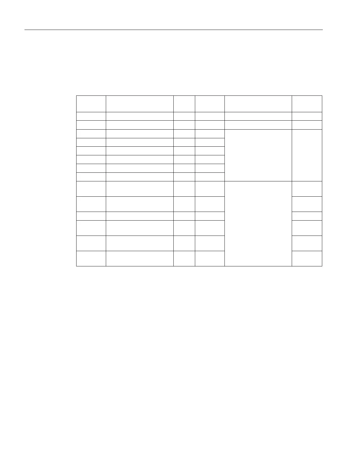
Structure of data record DS 143
The following overview shows the structure of the data record DS 143 in simplified form.
More detailed information about the structure of data record 143 is available in section
Structure for energy counters (DS 143) (Page 232).
1 Reserved BYTE - 0 -
- -
8...15 Start value for active en-
LREAL Wh
You will find the exact
assignment in the section
Structure for energy coun-
ters (DS 143) (Page 232).
61180
16...23 Initial value active energy
LREAL Wh 61181
158...161 Start value operating
REAL h 65505
162...165 Start value operating
REAL h 65506
166...169 Start value operating
REAL h 65507
Assignment of data record DS 143
Byte 0 and Byte 1: Version of the data record
Header information for the version of the data record.
Byte 2 ... Byte 7: Control bytes for energy and overflow counter
When data record 143 is written with the WRREC instruction, Bytes 2 to 7 are used as
phase-specific control information for energy meters, overflow counters and operating hours
counters. The length of the control information amounts to 2 bytes for each phase.
Byte 8 ... byte 157: Start values for the individual energy meters and overflow counters
The start values for energy counters in data record 143 are 64-bit floating point numbers.
The format corresponds to the data type LREAL in S7-1200 and in S7-1500.
The initial values for overflow counters in data record 143 are 16-bit integers. The format
corresponds to the data type UINT in S7-1200 and in S7-1500.
Byte 158 ... byte 169: Start values for operating hours counter
The start values for operating hours counters in data record 143 are 32-bit integers. The
format corresponds to the data type REAL in S7-1200 and in S7-1500.