EasyManua.ls Logo

Siemens SIMATIC IPC847D - Page 148

Siemens SIMATIC IPC847D
222 pages
To Next Page IconTo Next Page
To Previous Page IconTo Previous Page
Loading...
Technical specifications
8.5 Hardware description
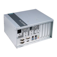
SIMATIC IPC847D
148 Operating Instructions, 01/2014, A5E32997454-AA
Pin no.
Short name
Meaning
Input / output
A10
Reserved
+ 5 V (fused) or ground
Configurable
USB2 (USB 2.0 contacts)
B1
-Data
Data channel USB2
Input / output
B2
+Data
Data channel USB2
Input / output
B3
GND
Ground
-
B4, 5
NC
Open
-
B6
GND
Ground
-
B7, 8
NC
Open
-
B9
VCC
+ 5 V (fused)
Output
B10
NC
Open
-
SATA data interface, X522, 523, 524, 525, 526, 527
Pin no.
Short name
Meaning
Input / output
1
GND
Ground
-
2
TX-P
Transmitter positive
Output
3
TX-N
Transmitter negative
Output
4
GND
Ground
-
5
RX-N
Receiver negative
Input
6
RX-P
Receiver positive
Input
7
GND
Ground
-
Pin assignment of the power supply fan monitoring interface, X514
Pin no.
Short name
Meaning
Input / output
1
Reserved
-
-
2
Reserved
PWM, speed setting ATX AC-SV
Output
3
Reserved
-
Input
4
Tacho signal
Monitoring signal
Input
5
PS_Status
Status of redundant power supply
Input
6 Reserved Reserved for fan error or redundant
power supply
Input
7 Quittung_Status Acknowledgment of acoustic alarm
signal of redundant power supply
(signal is open when module is
switched on)
Output
8
Ground
-
-

Table of Contents

Other manuals for Siemens SIMATIC IPC847D

Related product manuals