System integration
9.1 ASM 452
MOBY D
234 System Manual, 01/2010, J31069-D0147-A6-7618
9.1.4.4 PROFIBUS DP address and terminating resistor
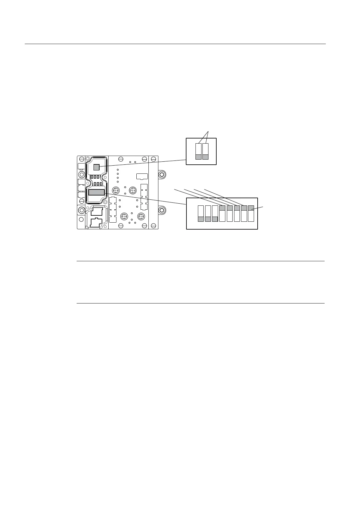
You must remove the connector plate from the ASM before you set the
PROFIBUS DP address or connect the terminating resistor. The connector plate covers the
DIL switch. The position of the DIL switch in ASM is shown in the figure below with one
setting example for each case.
21
2II
RQ
([DPSOH352),%86DGGUHVVRQGHOLYHU\
([DPSOH7HUPLQDWLQJUHVLVWRU2II
$VGHOLYHUHGVWDWH
6WDQGDUG
PRGH
XVH*6'ILOH
6,(0%
Figure 9-3 Setting the PROFIBUS DP address/connecting the terminating resistor
Note
The PROFIBUS DP address in ASM 452 must always match the PROFIBUS DP address
defined in the configuring software for this ASM.
To ensure that the terminating resistor functions correctly, you must always switch both
DIL switches of the terminating resistor to "on" or "off".