Mobile data storage units
5.2 Memory configuration of the ISO tags
MOBY D
98 System Manual, 01/2010, J31069-D0147-A6-7618
5.2 Memory configuration of the ISO tags
8VHUDUHD
UHDGZULWH
((3520
,&2'(6/,
E\WH((3520
E\WHEORFNVL]H
7DJLW+),
E\WH((3520
E\WHEORFNVL]H
,QILQHRQP\G
E\WH((3520
E\WHEORFNVL]H
E\WH)5$0
E\WHEORFNVL]H
E\WHV
8,'UHDGRQO\
0'6'
0'6'
0'6'
0'6'
0'6'
0'6'
0'6'
0'6'
0'6'
0'6'
0'6'
)))
)))
')
)
&)
))
)XMLWVX0%5
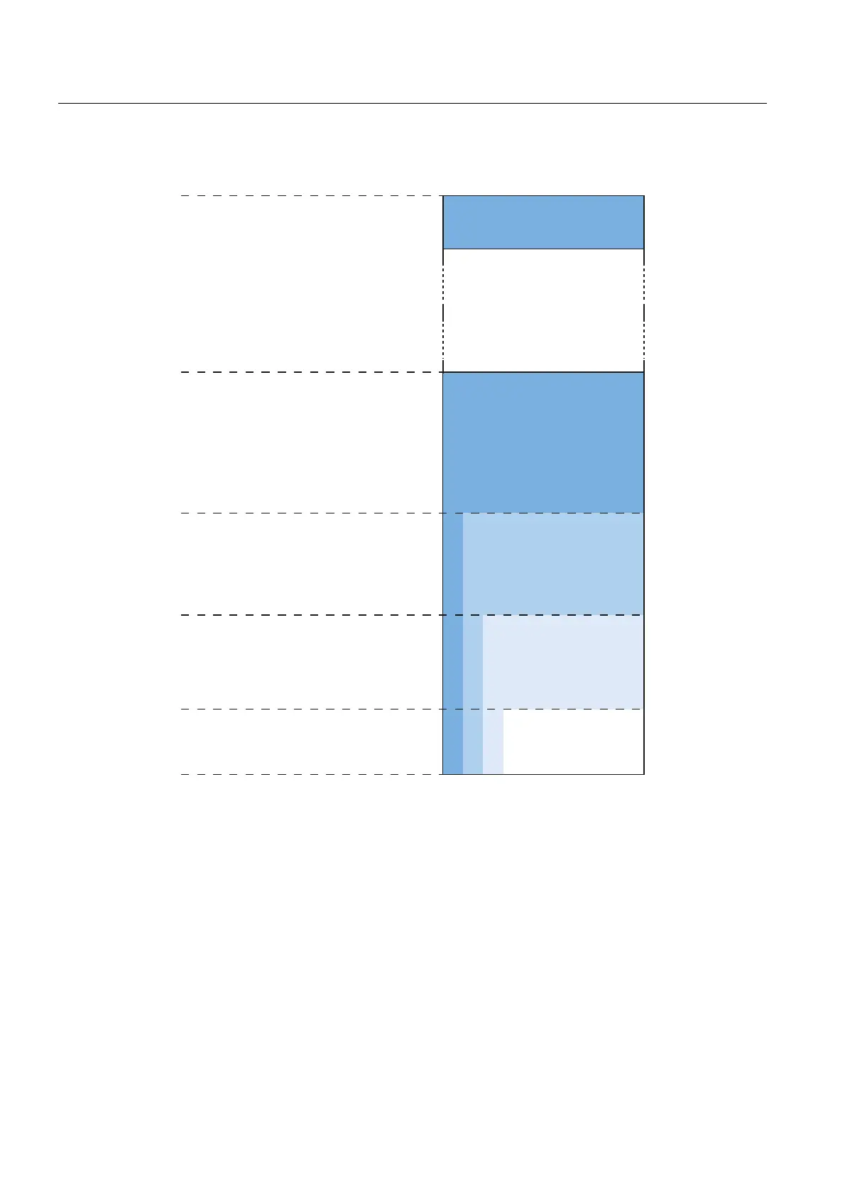
Figure 5-1 Memory configuration
Memory areas
Depending on the manufacturer of the transponder chip, the memory configuration of an ISO
tag consists of EEPROM memory of varying sizes. Except for transponders that are
equipped with a Fuijtsu 2k FRAM. These are equipped with one FRAM.
The typical sizes are 112 bytes, 256 bytes, 992 bytes or 2000 bytes. Each ISO transponder
chip features an 8-byte unique serial number (UID, read only). This UID is transferred as an
8 byte value through a read command to address FFF0 with a length of 8.