Planning the MOBY D system
4.2 Field data
MOBY D
System Manual, 01/2010, J31069-D0147-A6-7618
33
4.2 Field data
4.2.1 Field data for MDS and SLG
The field data of the MDS and SLG are shown in the table below. Thus it becomes
particularly easy to select the right MDS and SLG. All the technical specifications listed are
typical data and are applicable for the respective operating temperature of the MDS and SLG
used (see Technical data of the MDS and SLG used). Tolerances of ±20% are admissible
due to production and temperature conditions.
Note
In order to ensure optimum field data even in the vicinity of metal, ANT D5 is calibrated at
the factory at a distance of 100 mm from metal.
Note
The field data for the following MDS is only valid with a corresponding order number:
MDS D100 with order number 6GT2600-0AD10
MDS D124 with order number 6GT2600-0AC10
MDS D139 with order number 6GT2600-0AA10
MDS D160 with order number 6GT2600-0AB10
SLG D10/D10S with ANT D5
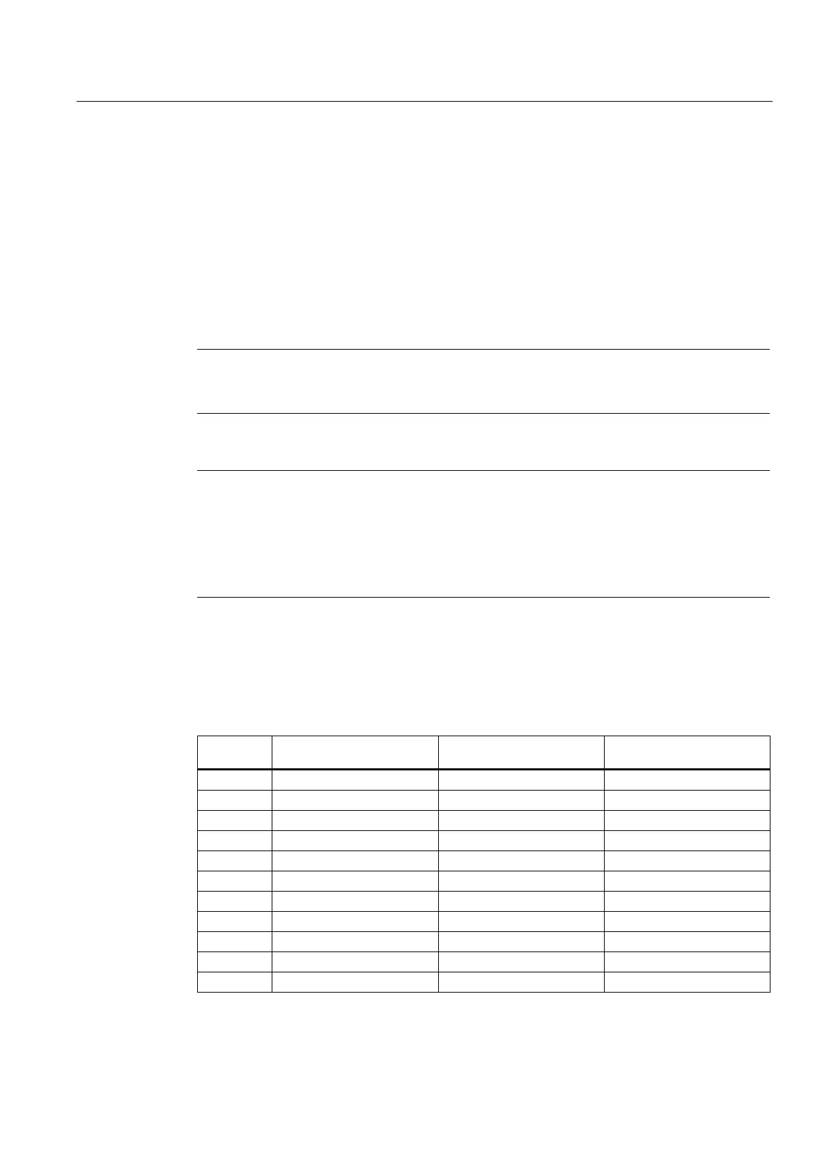
Table 4- 4 SLG D10/D10S with ANT D5
Diameter of the
transmission window (L
d
)
Operating distance (S
a
) Limit distance (S
g
)
MDS D100 ∅ 320 0...400 500
MDS D124 ∅ 300 0...200 280
MDS D139 ∅ 320 0...400 500
MDS D160 ∅ 300 0...130 180
MDS D324 ∅ 300 0...200 280
MDS D424 ∅ 300 0...200 280
MDS D428 ∅ 300 0...120 160
MDS D460 ∅ 300 0...120 160
MDS D165 ∅ 320 0...350 450
MDS D200 ∅ 320 0...400 500
MDS D261 ∅ 320 0...300 400
All values are in mm