System integration
9.4 ASM 475
MOBY D
System Manual, 01/2010, J31069-D0147-A6-7618
257
9.4.5 PROFIBUS DP communication
9.4.5.1 Diagnosis using LEDs
Display elements on the ASM
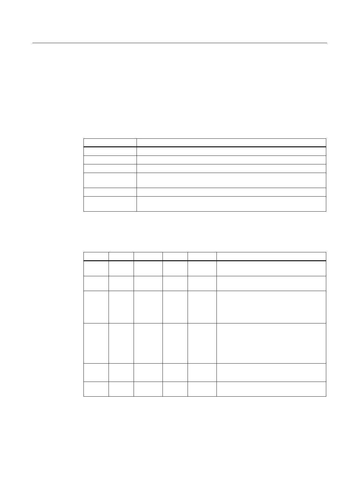
Table 9- 8 Function of the LEDs on the ASM 475
Light emitting diode Meaning
SF System fault (hardware error on ASM)
5 V DC 24 V are connected to the ASM and the 5 V voltage on the ASM is OK.
ACT_1, ACT_2 The corresponding write/read device is active in processing a user command.
ERR_1, ERR_2 A flashing pattern indicates the last error to occur. This display can be reset
using the parameter Option 1.
PRE_1, PRE_2 Indicates the presence of an MDS.
RxD_1, RxD_2 Indicates continuous communication to the SLG. Faults on the SLG can also
cause this indicator to be lit.
On the ASM 475, further operating states are indicated with the LEDs PRE, ERR and SF:
Table 9- 9 Operating status display on ASM 475 via LEDs
SF PRE_1 ERR_1 PRE_2 ERR_2 Meaning
ON OFF/ON ON
(perm.)
OFF/ON ON
(perm.)
Hardware is defective (RAM, Flash, etc.)
ON OFF ON OFF OFF Charger is defective (can only be repaired in
the factory).
OFF 2 Hz OFF 2 Hz OFF Firmware loading is active or no firmware
detected
Firmware download
ASM must not be switched off
OFF 2 Hz 2 Hz 2 Hz 2 Hz Firmware loading
terminated with errors
Restart required
Load firmware again
Check update files
Any 5 Hz 5 Hz 5 Hz 5 Hz Operating system error
Switch ASM off/on
OFF OFF 1 flash
every 2 s
OFF 1 flash
every 2 s
ASM has booted and is waiting for a RESET
(init_run) from the user.