Planning the MOBY D system
4.5 EMC Guidelines
MOBY D
System Manual, 01/2010, J31069-D0147-A6-7618
71
Line and signal filter
● Use only line filters with metal housings
● Connect the filter housing to the cabinet chassis using a large-area low-HF-impedance
connection.
● Never fix the filter housing to a painted surface.
● Fix the filter at the control cabinet inlet or in the direction of the source.
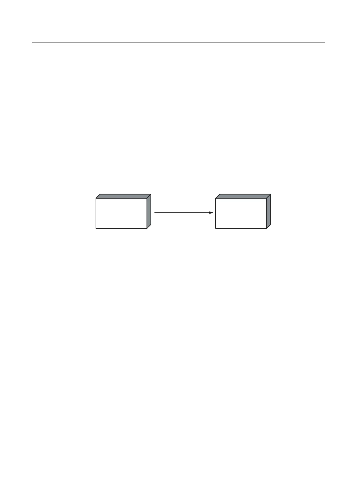
4.5.4 Propagation of electromagnetic interference
Three components have to be present for interference to occur in a system:
● Interference source
● Coupling path
● Interference sink
HJFRQQHFWLQJFDEOH
,QWHUIHUHQFHVRXUFH
GHYLFHHPLWWLQJ
LQWHUIHUHQFH
&RXSOLQJSDWK
HJGULYHXQLW HJUHDGHU
,QWHUIHUHQFHVLQN
GHYLFHDIIHFWHGE\
LQWHUIHUHQFH
Figure 4-22 Propagation of interference
If one of the components is missing, e.g. the coupling path between the interference source
and the interference sink, the interference sink is unaffected, even if the interference source
is transmitting a high level of noise.
The EMC measures are applied to all three components, in order to prevent malfunctions
due to interference. When setting up a plant, the manufacturer must take all possible
measures in order to prevent the occurrence of interference sources:
● Only devices fulfilling limit class A of VDE 0871 may be used in a plant.
● Interference suppression measures must be introduced on all interference-emitting
devices. This includes all coils and windings.
● The design of the system must be such that mutual interference between individual
components is precluded or kept as small as possible.
Information and tips for plant design are given in the following sections.