Planning the MOBY D system
4.5 EMC Guidelines
MOBY D
System Manual, 01/2010, J31069-D0147-A6-7618
79
4.5.7 Equipotential bonding
Potential differences between different parts of a plant can arise due to the different design
of the plant components and different voltage levels. If the plant components are connected
across signal cables, transient currents flow across the signal cables. These transient
currents can corrupt the signals.
Proper equipotential bonding is thus essential.
● The equipotential bonding conductor must have a sufficiently large cross section (at least
10 mm
2
).
● The distance between the signal cable and the associated equipotential bonding
conductor must be as small as possible (antenna effect).
● A fine-strand conductor must be used (better high-frequency conductivity).
● When connecting the equipotential bonding conductors to the centralized equipotential
bonding strip (EBS), the power components and non-power components must be
combined.
● The equipotential bonding conductors of the separate modules must lead directly to the
equipotential bonding strip.
&DELQHW &DELQHW
,QFRUUHFW
3RZHUVXSSO\
'ULYH
'HYLFH
3/&
(%6
'HYLFH
'HYLFH
,QFRUUHFW
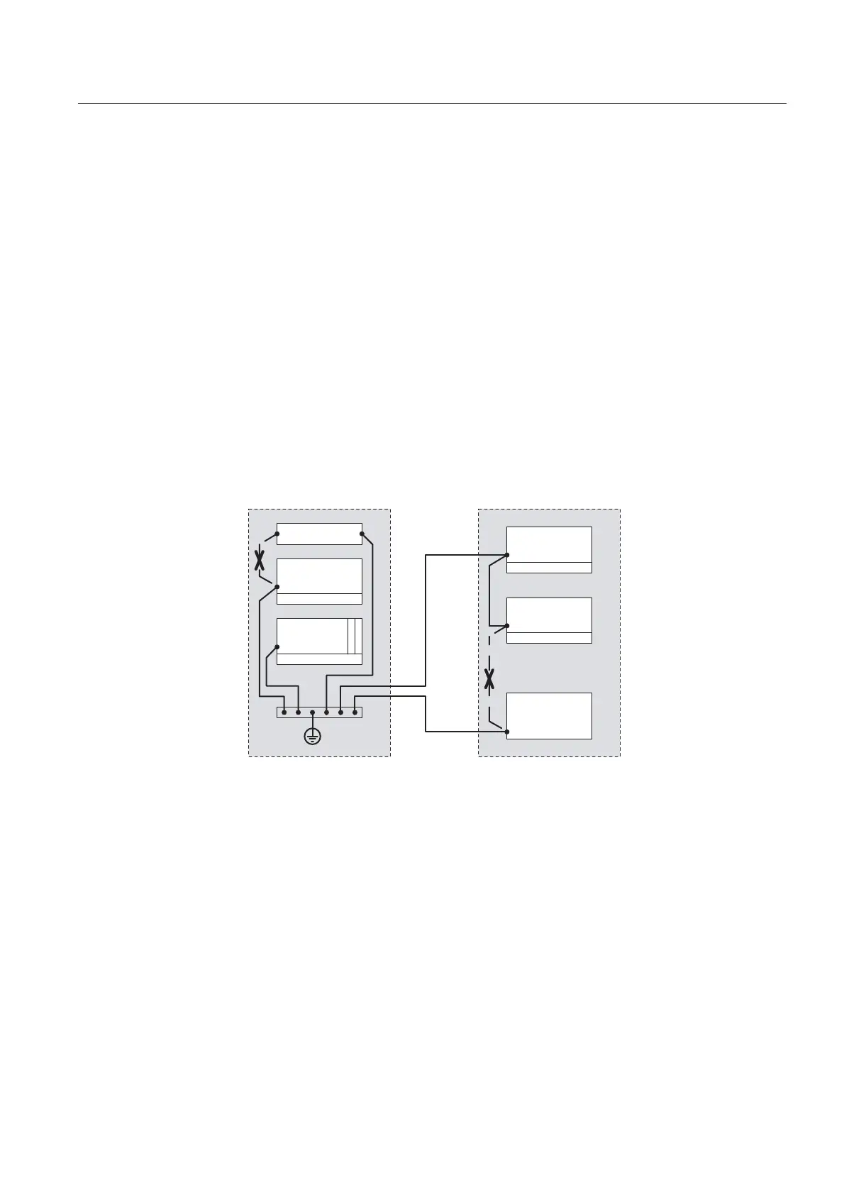
Figure 4-28 Equipotential bonding (EBS = Equipotential bonding strip)
The better the equipotential bonding in a plant, the smaller the chance of interference due to
fluctuations in potential.
Equipotential bonding should not be confused with protective earthing of a plant. Protective
earthing prevents the occurrence of excessive shock voltages in the event of equipment
faults whereas equipotential bonding prevents the occurrence of differences in potential.