Interrupt details
The bytes starting from x+8 inform you of the interrupt details. Interrupt details of modules
whose identifiers (byte x+8) are not listed here can be obtained from the respective module
documentation.
Note
The channel fault vector (byte x + 11) has a length of at least 1 byte. For modules with more than
8 channels, the channel fault vector occupies multiple bytes accordingly.
If another channel type is present, the first diagnostic data record is followed by an identically
structured record for the next channel type.
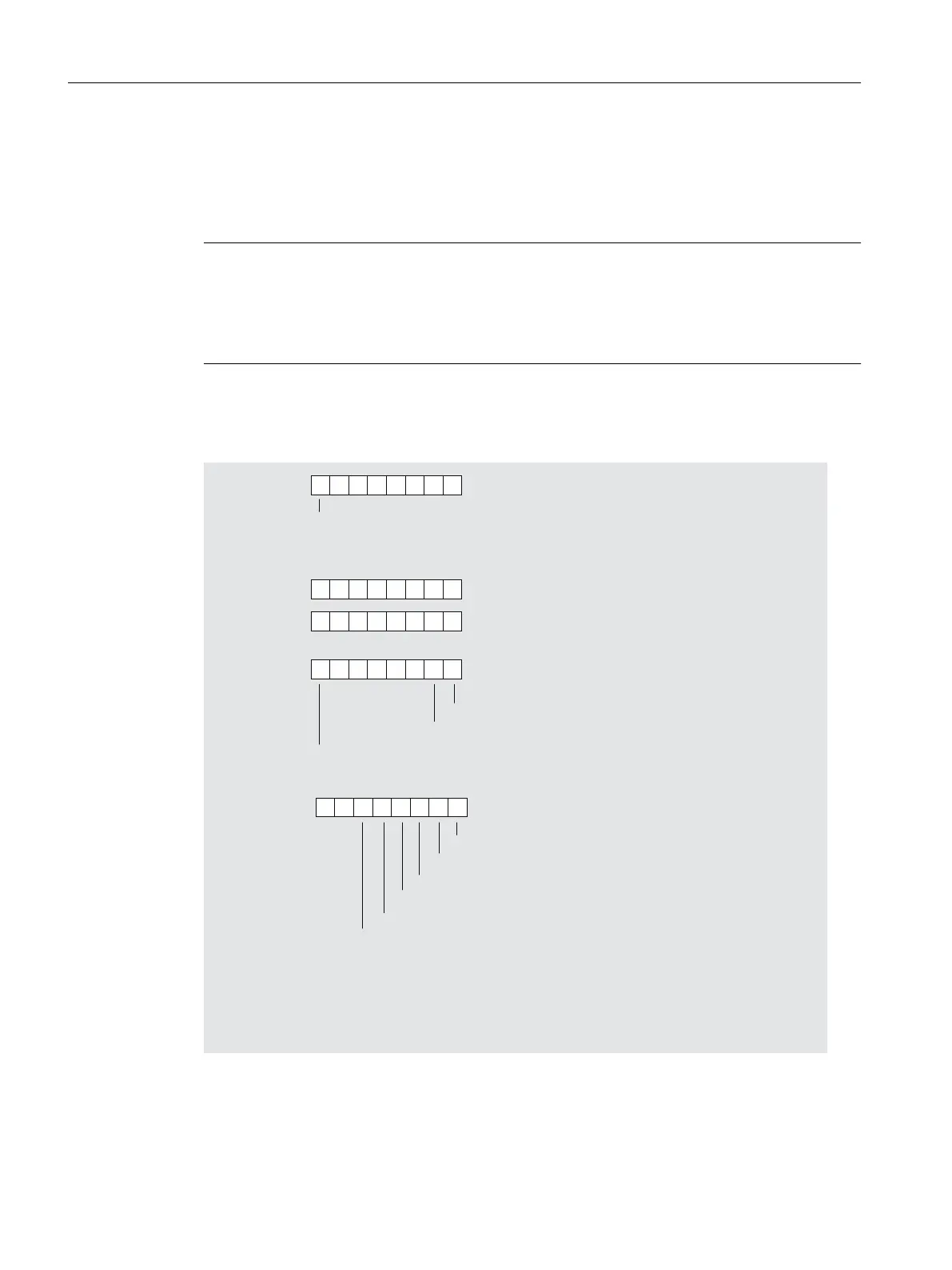
Interrupt details of modules with digital inputs
+
0RGXOHZLWKGLJLWDOLQSXWV
/HQJWKRIWKHFKDQQHOVSHFLILFGLDJQRVWLFVLQELWV
ELWV
1XPEHURIFKDQQHOVSHUPRGXOH
'LDJQRVWLFHYHQWDWFKDQQHOFKDQQHOJURXSRIWKHPRGXOH
'LDJQRVWLFHYHQWDWFKDQQHOFKDQQHOJURXSRIWKHPRGXOH
'LDJQRVWLFHYHQWDWFKDQQHOFKDQQHOJURXSRIWKHPRGXOH
'LDJQRVWLFHYHQWVIRUFKDQQHOFKDQQHOJURXS
&RQILJXUDWLRQSDUDPHWHUDVVLJQPHQWHUURU
%
1RDGGLWLRQDOFKDQQHOW\SHSUHVHQWLQWKHGLDJQRVWLFV
%
$QDGGLWLRQDOFKDQQHOW\SHLVSUHVHQWLQWKHGLDJQRVWLFV
*URXQGHUURU
6KRUWFLUFXLWWR/VHQVRU
6KRUWFLUFXLWWR0
:LUHEUHDN
1RVHQVRUSRZHUVXSSO\
$VVLJQPHQWIRUFKDQQHOFKDQQHOJURXSVDPHDVE\WH[
$VVLJQPHQWIRUFKDQQHOFKDQQHOJURXSVDPHDVE\WH[
$VVLJQPHQWIRUFKDQQHOFKDQQHOJURXSVDPHDVE\WH[
&KDQQHOHUURUYHFWRU
%\WH[
%\WH[
%\WH[
%\WH[
%\WH[
%\WH[
%\WH[
%\WH[
Figure 8-9 Structure starting from byte x+8 for diagnostic interrupt (digital inputs)
Interrupt, error and system messages
8.3 S7 diagnostics
ET 200PA SMART
108 Operating Instructions, 06/2019, A5E34192013-AB
 Loading...


