4. Release the front connector and remove it.
– For 20‑pin front connector: Use one hand to press the release button down (4) and use
your other hand to withdraw the front connector using the grips (4a).
– For 40‑pin front connector: Loosen the fixing screw in the center of the front connector.
Withdraw the the front connector using the grips.
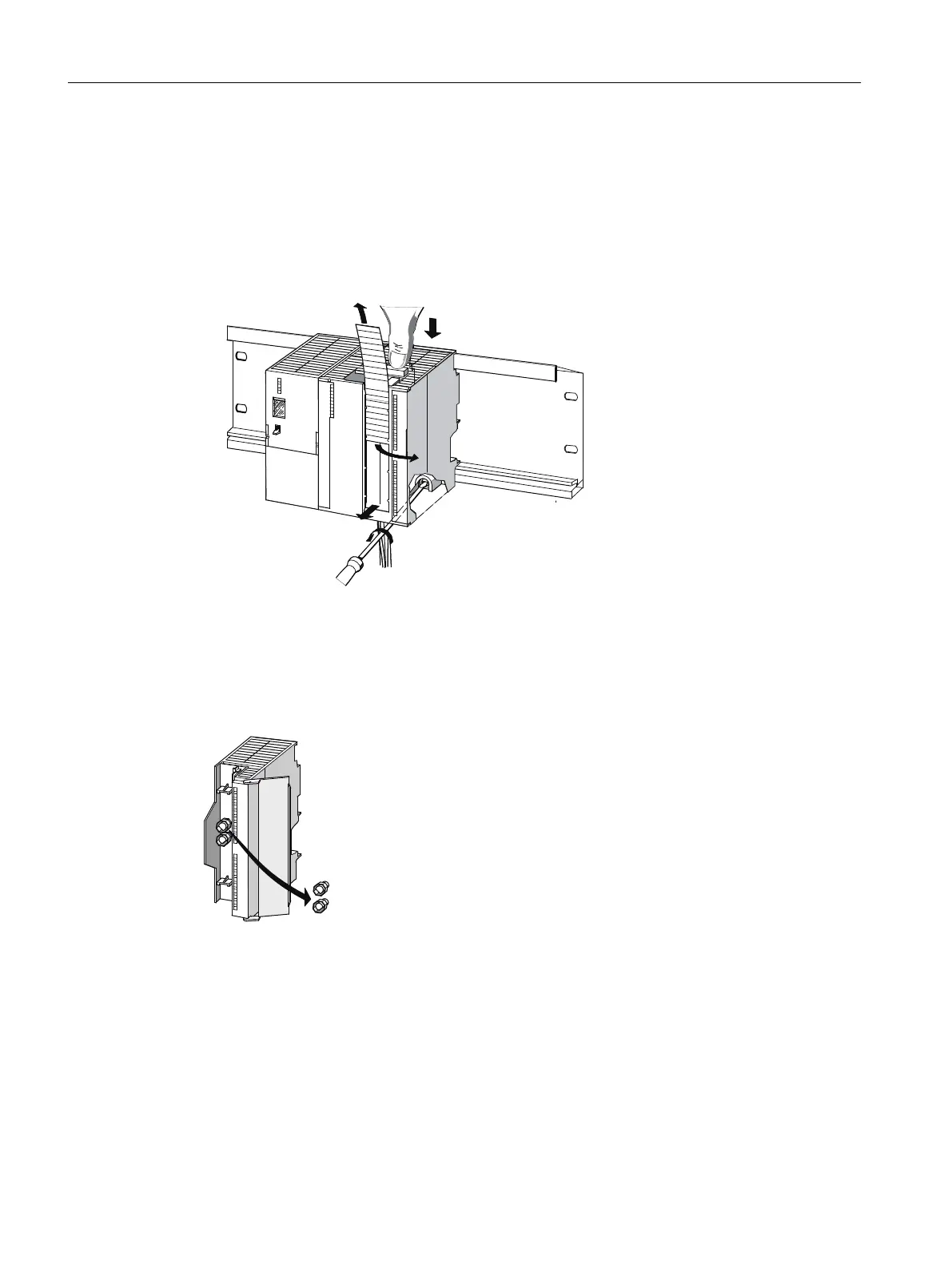
5. Remove the labeling strip from the module.
Removing the front connector coding
Prior to installing the new module you must remove the top part of the front connector coding
on the module. Reason: This part is already available in the wired front connector (refer to the
following figure).
Figure 6-1 Removing the front connector coding
Installing a new module
Proceed as follows to install a new module:
1. Insert the front connector in the module and put it into operating position.
2. Hook in the new module and swing it downwards.
3. Screw the module into place.
4. Slide the labeling strip of the removed module into the newly installed module.
Maintenance and service
6.4 Replacing I/O modules
ET 200PA SMART
64 Operating Instructions, 06/2019, A5E34192013-AB
 Loading...


