ET 200PA SMART in the overall configuration
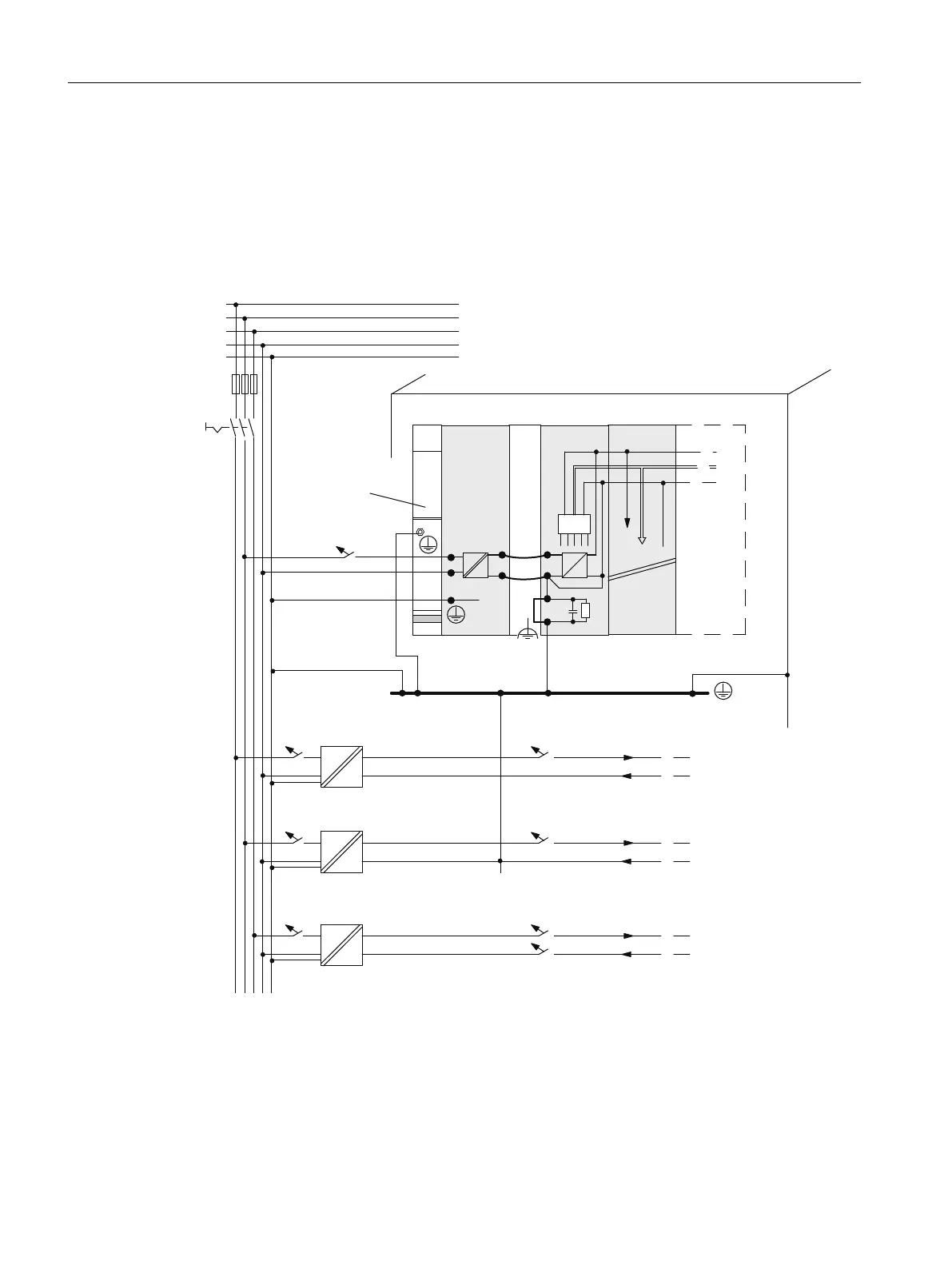
The following figure shows the position of the ET 200PA SMART in the overall configuration
(load power supply and grounding concept) with supply from a TN-S system.
Note: The arrangement of the supply connections shown does not correspond to the actual
arrangement; it was chosen to give you a clear overview.
$&
$&
$&
'&
$&
'&
w3
1
0
/
/
0
36
60)0
,0
/
/
/
1
3(
/RZYROWDJHGLVWULEXWLRQ
HJ716V\VWHP[9
0RXQWLQJUDLO
&DELQHW
*URXQGEXVLQFDELQHW
/RDGFLUFXLW
WR9$&IRU$&PRGXOHV
/RDGFLUFXLWWR9'&IRU
QRQLVRODWHG'&PRGXOHV
/RDGFLUFXLWWR9'&IRU
LVRODWHG'&PRGXOHV
Figure 2-5 Operating ET 200PA SMART modules or S7‑300 modules from grounded supply
ET 200PA SMART with load power supply from PS 307
The following figure shows the position of the ET 200PA SMART in the overall configuration
(load power supply and grounding concept) with supply from a TN-S system.
Assignment planning
2.3 Configuring the electrical structure
ET 200PA SMART
26 Operating Instructions, 06/2019, A5E34192013-AB
 Loading...


