3.3 Setting the PROFIBUS address
Definition
Each bus node must receive a PROFIBUS address to identify it uniquely on the PROFIBUS
DP.
Rules
The following rules apply for the PROFIBUS address of the IM 650:
● Permissible PROFIBUS addresses are: 1 to 125.
● Each PROFIBUS address can be allocated only once on the bus.
Setting the PROFIBUS address
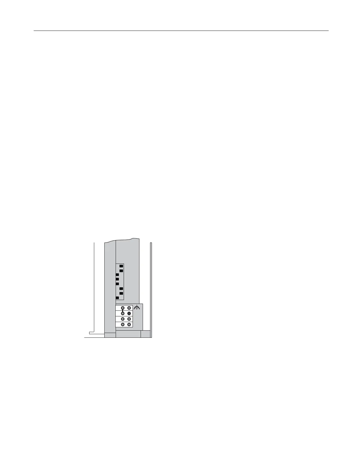
1. Set the PROFIBUS address using a screwdriver and with the door open.
The PROFIBUS address is the addition of the switch that is located on the right ("ON"
position).
Example: Setting the PROFIBUS address
%86
21
0
/
0
'&9
$''5
ಥ
PROFIBUS address:
64 + 32 + 2 + 1 = 99
The switch "-" has no function.
Changing the PROFIBUS address
You can change the set PROFIBUS address at any time. However, the IM 650 adopts the new
PROFIBUS address only after a switch off / switch on of the 24 V DC supply.
Installation
3.3 Setting the PROFIBUS address
ET 200PA SMART
Operating Instructions, 06/2019, A5E34192013-AB 39
 Loading...


