3.2.4 After installation
Assigning slot numbers
After installation, you can assign a slot number to each module. The following table illustrates
the assignment of the slots.
Table 3-2 Slot numbers
Slot number Module Remark
1 Power supply (PS)
1
–
2 IM 650 –
3 – Not applicable
4 Module 1 Directly to the right of IM 650
5 Module 2 –
… … –
15 Module 12 –
1
The use of the power supply is optional.
Unoccupied slots
In a configuration of an ET 200PA SMART with active bus modules, if slots are unoccupied (e.g.
reserved for later use), you must leave these slots free when configuring!
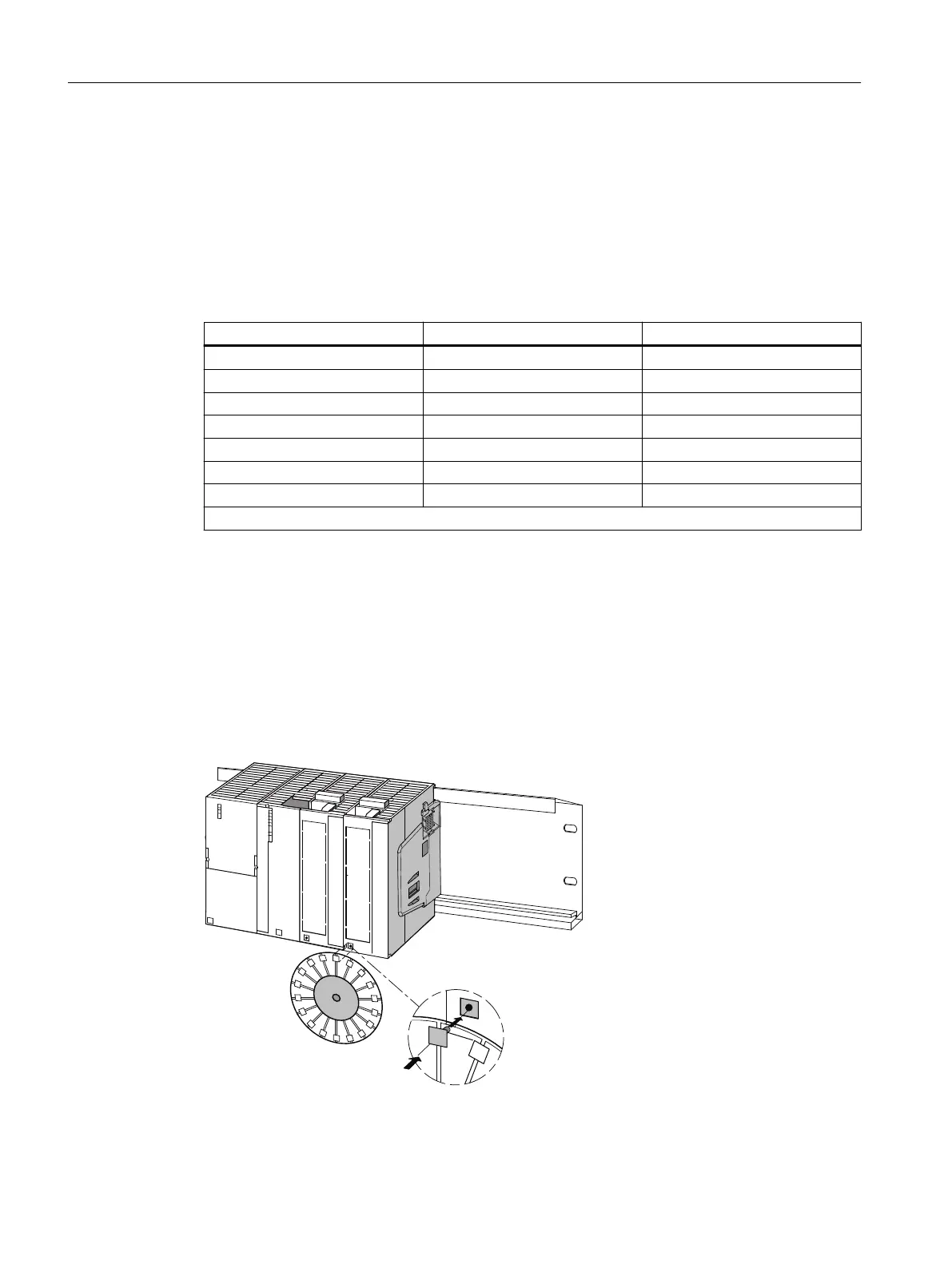
Attaching slot numbers
The following figure shows how you must attach the slot numbers. The slot number plates are
provided with the IM 650.
Figure 3-3 Attaching the slot numbers to the modules.
Installation
3.2 Installation
ET 200PA SMART
38 Operating Instructions, 06/2019, A5E34192013-AB
 Loading...


