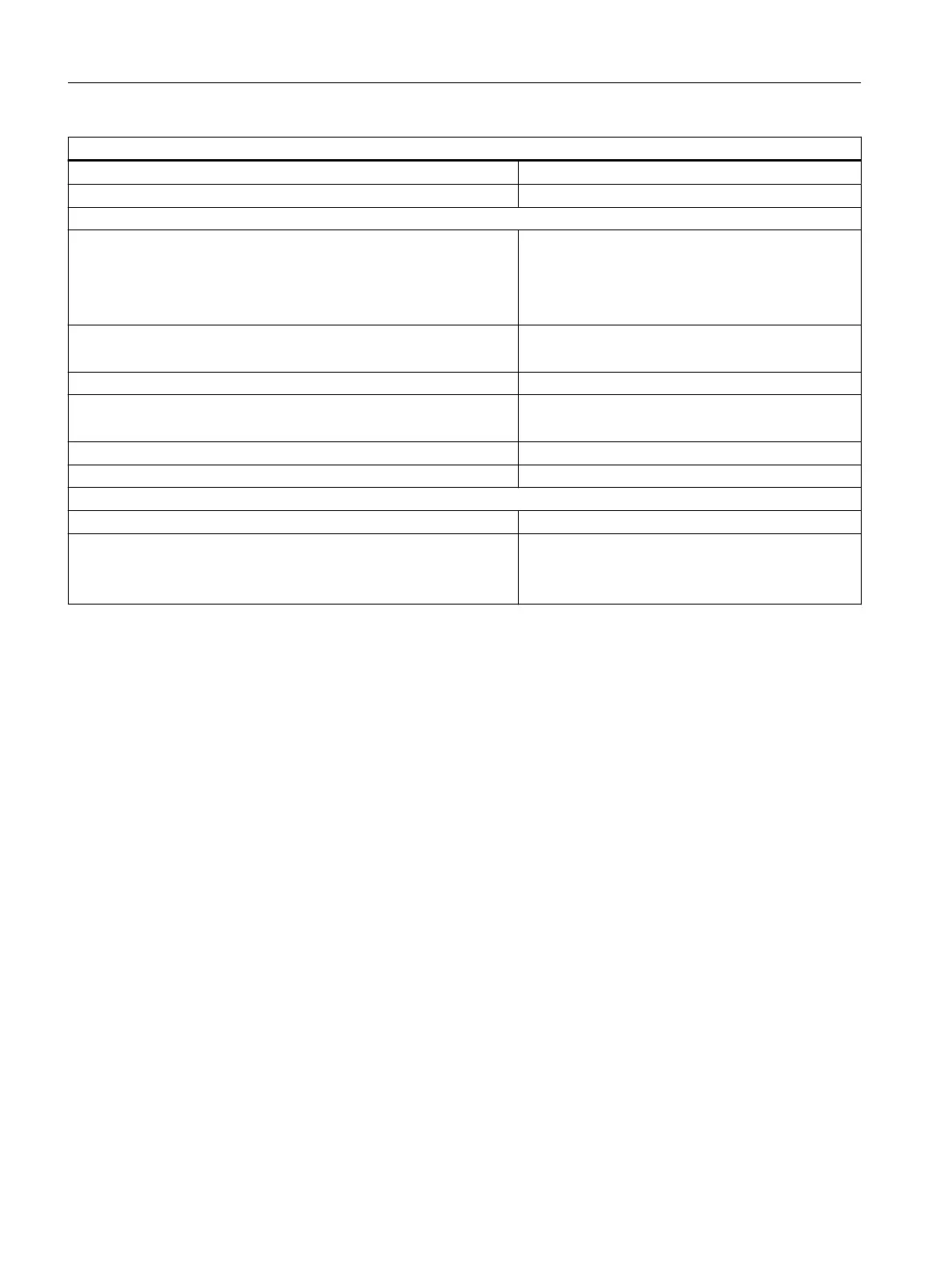
Technical specifications
Additional (redundant) supply Permitted
Short-circuit protection Yes, electronic
Sensor selection data
Input voltage
● Rated value
● For "1" signal
● For "0" signal
24 V DC
From 13 to 30 V
From - 30 to + 5 V
Input current
● When signal "1" is present
Typ. 7 mA
Input characteristics According to IEC 61131, Type 2
Connection of 2-wire BEROs
● Permissible quiescent current
Supported
Max. 2 mA
Connection of the transducer Using a 20-pin front connector
Resistance circuit of the sensor for wire-break detection 10 to 18 kilohm
Time/frequency
Internal preparation time for diagnostics Max. 40 ms
Input delay
● Configurable
● Rated value
Yes
Typ. 0.1/0.5/3/15/20 ms
10.2.2.1 Parameters of the DI 16 x DC 24 V
Parameter assignment
The parameters are assigned using the parameter assignment dialog of HW Config
Parameters of the DI 16 x DC 24 V
The table below provides an overview of the assignable parameters and their default settings
for the DI 16 x DC 24 V.
ET 200PA SMART I/O modules
10.2 Digital input modules
ET 200PA SMART
134 Operating Instructions, 06/2019, A5E34192013-AB
 Loading...


