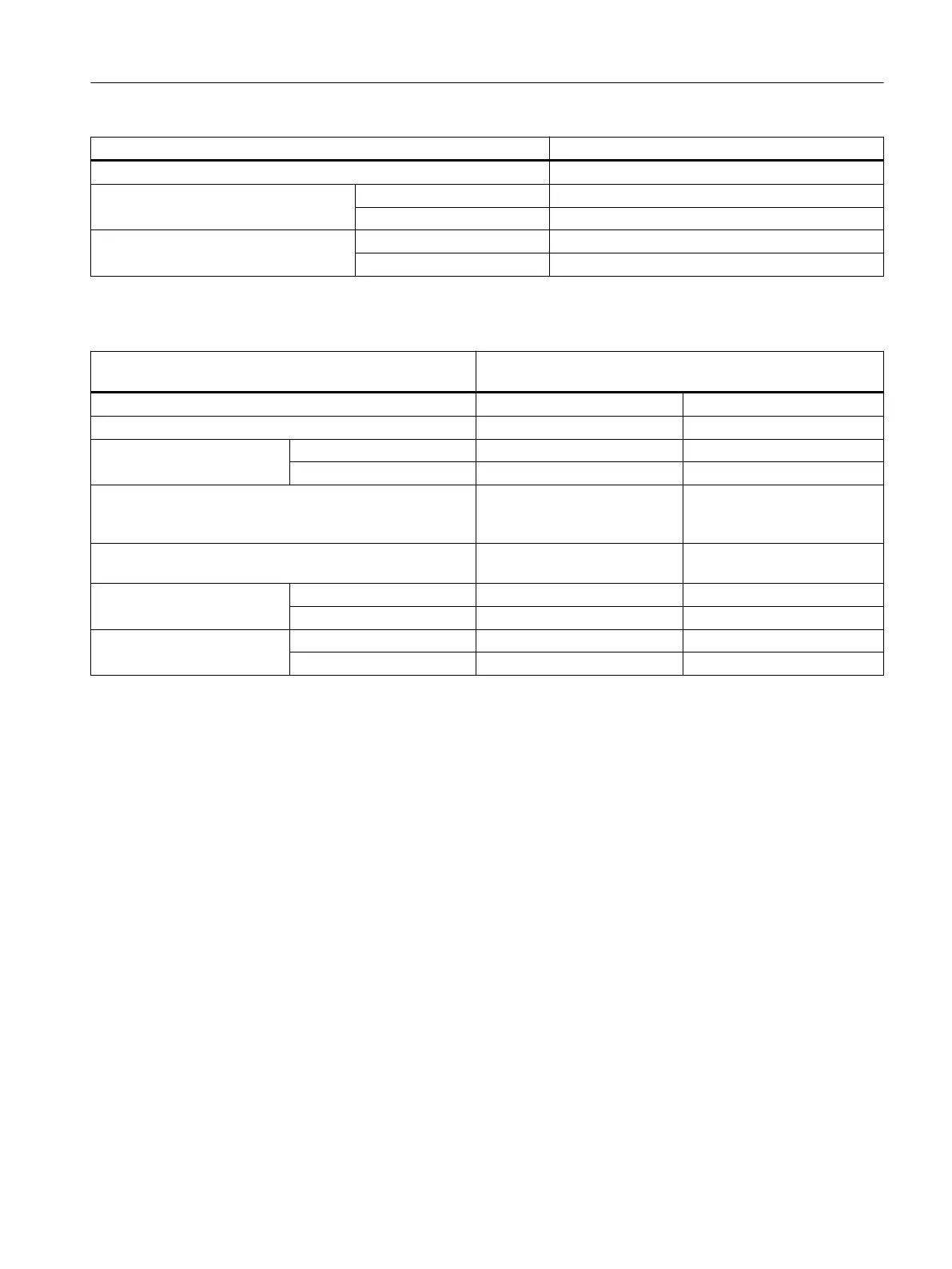
Wiring rules for ... Power supply and IM 650
Maximum external diameter of the cable isolation Ø 3.8 mm
Isolation stripping length of the cables without isolation collar 11 mm
with isolation collar 11 mm
End sleeves in accordance with DIN
46228
without isolation collar Form A, 10 to 12 mm long
with isolation collar Form E, up to 12 mm long
Table 4-2 Wiring rules for front connectors of modules
Wiring rules for ... Front connectors of modules
(screw-type and spring-loaded terminals)
20‑pin 40‑pin
Connectable cable cross-sections for solid cables No No
Connectable cable cross-sec‐
tions for flexible cables
without end sleeve 0.25 to 1.5 mm
2
0.14 to 0.75 mm
2
with end sleeve 0.25 to 1.5 mm
2
0.14 to 0.75 mm
2
Number of cables per connection 1 or a combination of 2 conduc‐
tors up to 1.5 mm
2
(total) in a
common end sleeve
1 or combination of 2 conduc‐
tors up to 0.75 mm
2
(total) in a
common end sleeve
Maximum external diameter of the cable isolation Ø 3.1 mm
max. 20 cables
Ø 2.0 mm
max. 40 cables
Isolation stripping length of
the cables
without isolation collar 6 mm 6 mm
with isolation collar 6 mm 6 mm
End sleeves in accordance
with DIN 46228
without isolation collar Form A, 5 to 7 mm long Form A, 5 to 7 mm long
with isolation collar Form E, up to 6 mm long Form E, up to 6 mm long
4.3.2 Wiring the power supply and IM 650
Power cables
Use flexible cables to wire the power supply.
If you use only one cable per connection, an end sleeve is not required.
Connecting comb
Use the connecting comb to wire the PS 307 power supply module with the IM 650. The
connecting comb comes with the power supply module.
Further 24 V connections
On the PS 307 power supply, 24 V connections are still available, by means of the connecting
comb, for connecting the supply of the ET 200PA SMART modules.
Connecting
4.3 Wiring the power supply and modules
ET 200PA SMART
Operating Instructions, 06/2019, A5E34192013-AB 43
 Loading...


