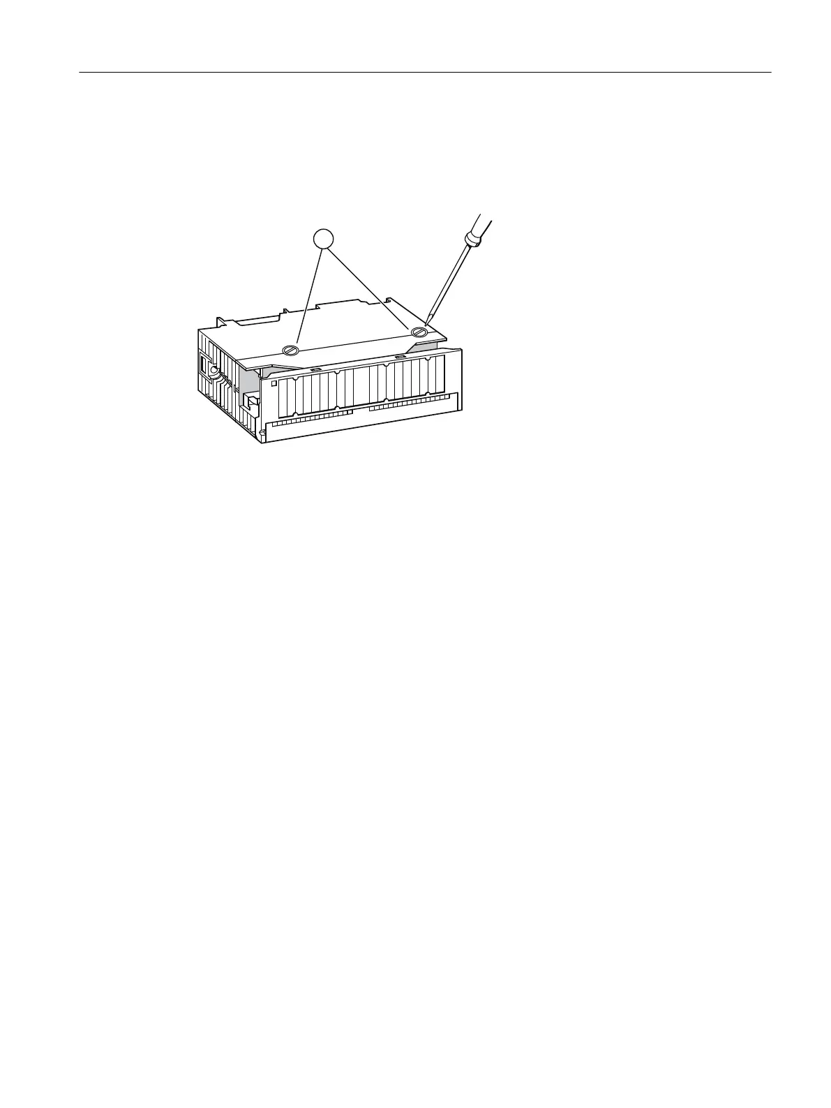
Position of the fuses
The digital output modules have one fuse per channel group. The fuses are located at the left
side of the digital output module. The figure shows you where to find the fuses on the digital
output modules.
① Fuses
Figure 6-2 Location of the fuses on digital output modules
Replacing a fuse
The fuses are located on the left side of the module.
1. Dismantle the digital output module.
2. Screw the fuse holder from the digital output module.
3. Replace the fuse.
4. Screw the fuse holder back into the digital output module.
5. Install the digital output module again.
6.7 Update of the IM 650
6.7.1 When should you update the IM 650?
After addition of (compatible) functions or improvements of performance, you should update
the IM 650 interface module to the latest firmware version.
Maintenance and service
6.7 Update of the IM 650
ET 200PA SMART
Operating Instructions, 06/2019, A5E34192013-AB 67
 Loading...


