Diagnostic messages and possible corrective measures
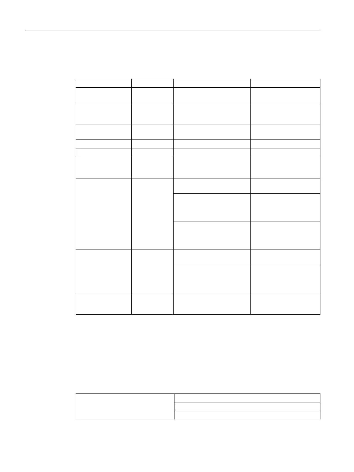
Table 10-18 Diagnostic messages of AI 8 x TC/4 x RTD and possible remedial measures
Diagnostic message Configurable Possible cause of error Corrective measure
Module parameters
not assigned
No Startup error Reassign the module pa‐
rameters
Incorrect parameters No One parameter, or the combi‐
nation of parameters, is not
plausible
Reassign the module pa‐
rameters
Time monitoring trip‐
ped
No Intermittently high electromag‐
netic interference
Eliminate the interference
EPROM error No Module defective Replace the module
RAM error No Module defective Replace the module
Parameter assign‐
ment error
No One parameter, or the combi‐
nation of parameters, is not
plausible
Reassign the module pa‐
rameters
Wire break Yes The connection of the trans‐
ducer is interrupted
Check the wiring
Resistance of sensor protec‐
tion circuit too high
Use a different type of sen‐
sor or modify the wiring, for
example, use cables with
larger cross-section
Channel not connected (open) Disable the channel group
("Measurement type" pa‐
rameter) or connect the
channel
Low limit violation of
measuring range / un‐
derrange
Yes
(group diagnos‐
tics)
Analog value below the under‐
range
Check the measuring range
selection
In the case of measuring range
4 mA to 20 mA, sensor may be
connected with reverse polari‐
ty.
Check terminals
High limit violation of
measuring range / un‐
derrange
Yes
(group diagnos‐
tics)
Analog value above the over‐
range
Assign a different measur‐
ing range
10.5 Analog output modules
Overview of properties
The table below presents the ET 200PA SMART analog output module based on its most
important properties.
Properties Module
AO 8 x 12 Bit
6ES7 650-8BK60-xAA0
ET 200PA SMART I/O modules
10.5 Analog output modules
ET 200PA SMART
200 Operating Instructions, 06/2019, A5E34192013-AB
 Loading...


