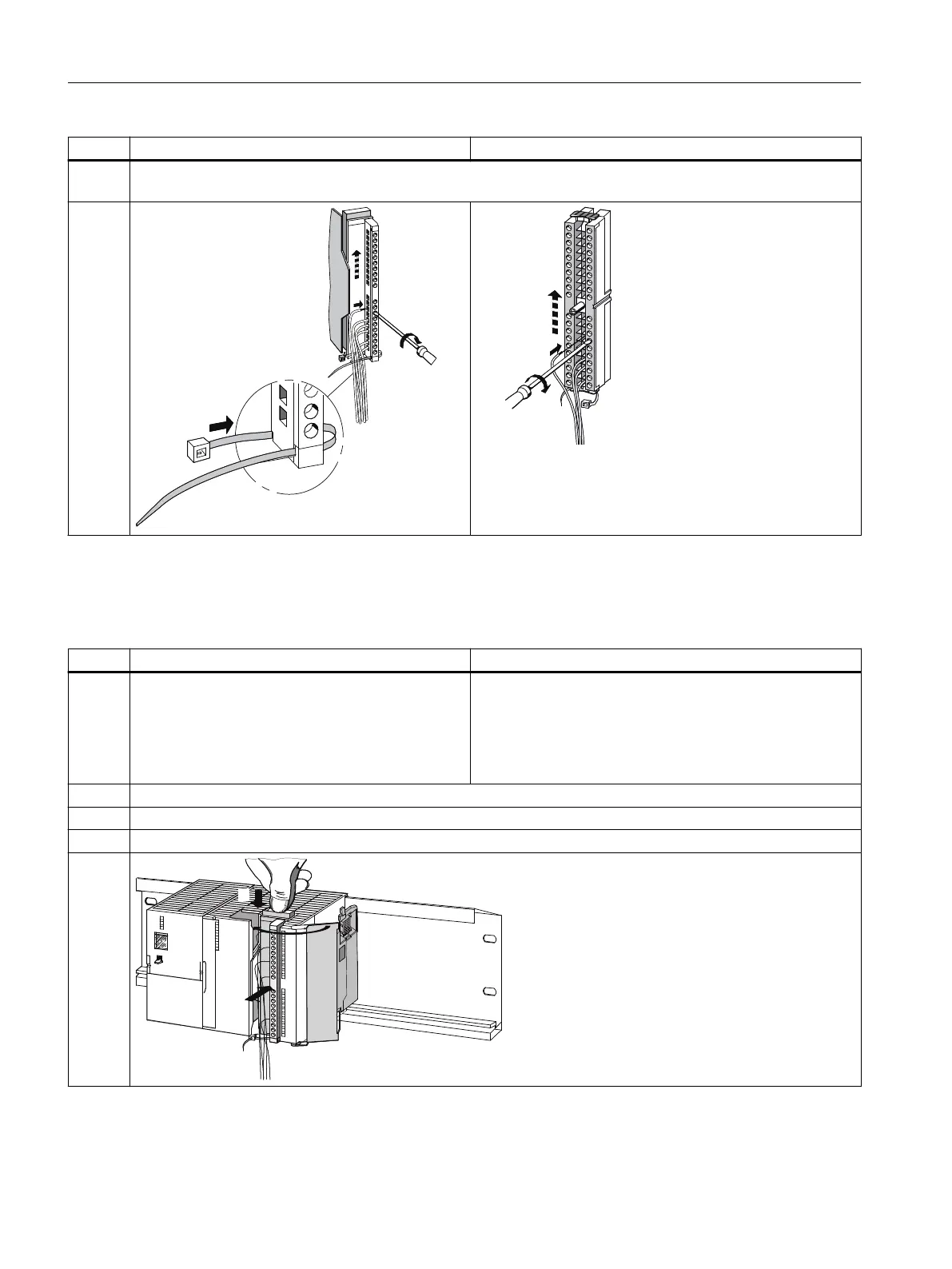
Step 20‑pin front connector 40‑pin front connector
5. Tighten the strain relief for the cable string. Press the retainer of the strain relief in and to the left; this will improve
utilization of the available space.
—
Preparing the signal module for operation
Table 4-4 Preparing the signal module for operation
Step 20‑pin front connector 40‑pin front connector
1. Press down the unlocking button on the top of the
module and, at the same time, push the front con‐
nector into its operating position on the module.
When the front connector reaches its operating po‐
sition, the unlocking button will snap back into the
initial position.
Tighten the fixing screw to bring the front connector to its
operating position.
2. Close the front door.
3. Enter the addresses for identifying the individual channels on the labeling plate.
4. Slide the labeling plate into the front door.
—
Connecting
4.3 Wiring the power supply and modules
ET 200PA SMART
48 Operating Instructions, 06/2019, A5E34192013-AB
 Loading...


