Technical specifications
● For performance increase
Not supported
Control of a digital input Supported
Switching frequency
● With resistive load
Max. 100 Hz
● With inductive load according to IEC 947-5-1, DC 13
Max. 2 Hz
● With lamp load
Max. 10 Hz
Internal limiting of the inductive trip voltage to Typ. L+ (-68 V)
Short-circuit protection of the output Yes, electronic
● Response threshold
Typ. 1.4 A
Connection of the actuators Using a 40-pin front connector
10.3.2.1 Parameters of the DO 16 x DC 24 V/0.5 A
Parameter assignment
The parameters are assigned using the parameter assignment dialog of HW Config
Parameters of the DO 16 x DC 24 V/0.5 A
The table below provides an overview of the assignable parameters and their default settings
for the DO 16 x DC 24 V/0.5 A.
The default settings apply when you have not assigned parameters in HW Config or you have
not changed any parameters.
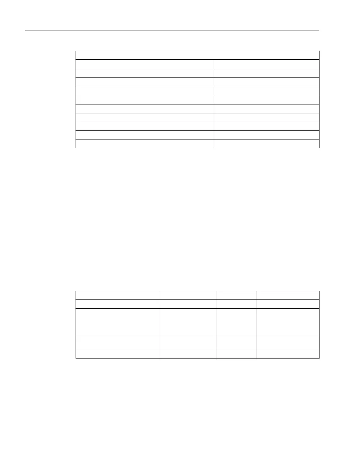
Table 10-6 Parameters of the DO 16 x DC 24 V/0.5 A
Parameter Value range Default setting Scope
Diagnostic interrupt enable Yes / No Yes Module
Diagnostics
● Group diagnostics
● No load voltage L+
Yes / No
Yes / No
Yes
Yes
Channel
Channel group
Reaction to CPU/master STOP Substitute a value/
Keep last value
Substitute a
value
Module
Substitute value 0/1 0 Channel
Group diagnostics
The diagnostics parameter "Group diagnostics" enables the signaling of channel-specific
errors to be switched off, with the exception of parameter assignment errors.
ET 200PA SMART I/O modules
10.3 Digital output modules
ET 200PA SMART
146 Operating Instructions, 06/2019, A5E34192013-AB
 Loading...


