Connection diagram
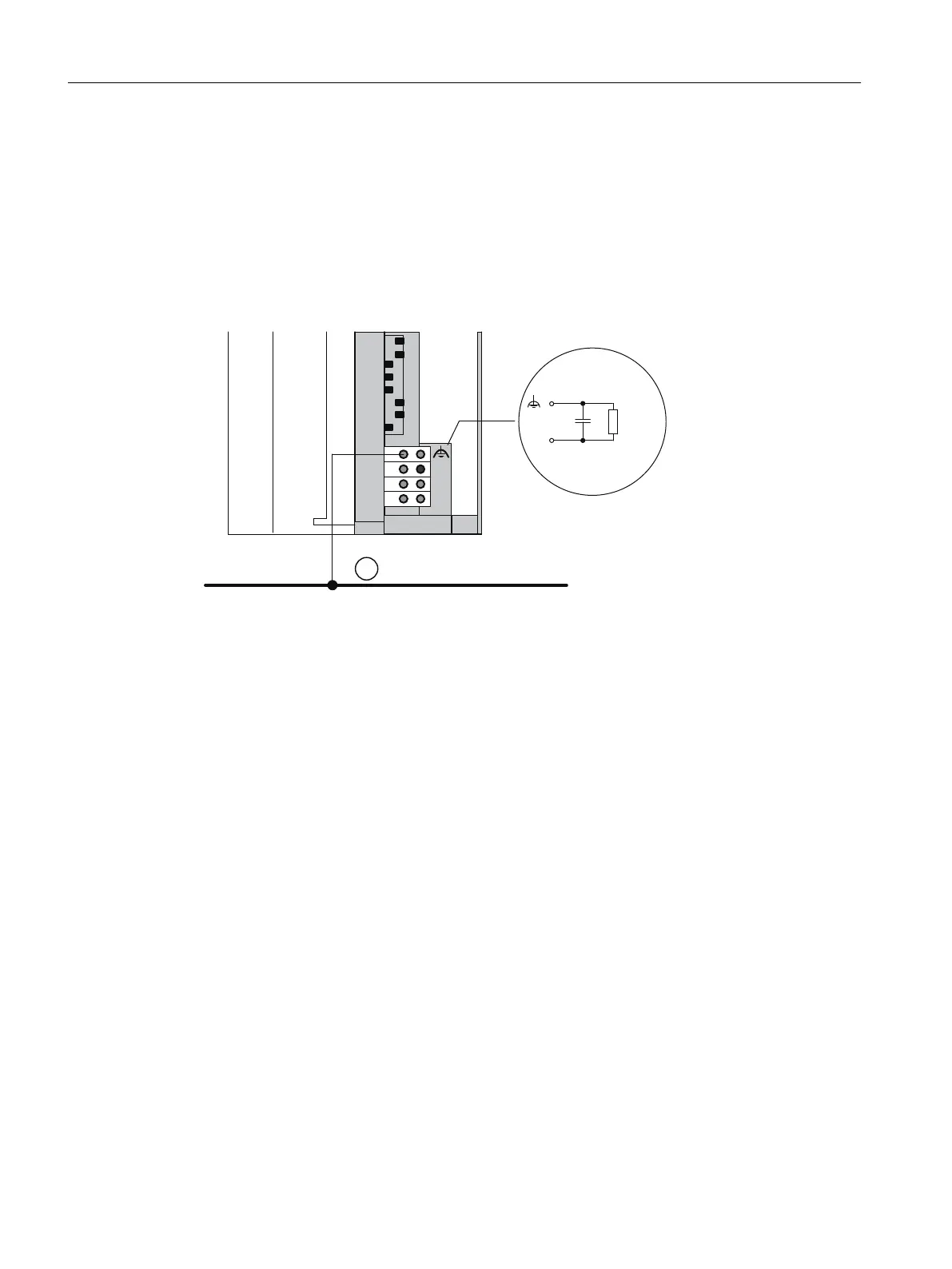
The following figure shows the configuration of an ET 200PA SMART with IM 650 and
ungrounded reference potential. If you don´t want to ground the reference potential, then you
must remove the jumper on the IM 650 between the M and functional ground terminals. When
the jumper is removed, the reference potential of the ET 200PA SMART is connected internally
to the protective conductor via an RC combination and via the mounting rail. This way, high-
frequency interference currents are discharged and static charges are prevented.
1
'&9
0
/
0
0
Q)0˖
Figure 2-7 Configuration of an ET 200PA SMART with ungrounded reference potential
① Ground bus
Power supplies
When using power supplies, ensure that the secondary winding is not connected to the
protective conductor. We recommend use of the PS 307 power supply module.
Filtering the 24 V DC supply
If, with a configuration with ungrounded reference potential, you supply the IM 650 from a
battery, you must suppress interference in the 24 V DC power supply. To do this, use a
Siemens supply cable filter, e.g. B84102‑K40.
Isolation monitoring
If, on account of double faults, dangerous situations could occur, then you must provide
isolation monitoring.
Assignment planning
2.3 Configuring the electrical structure
ET 200PA SMART
28 Operating Instructions, 06/2019, A5E34192013-AB
 Loading...


