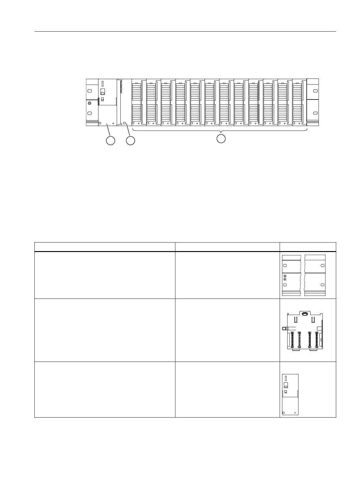
Configuration of an ET 200PA SMART
① Power supply module PS 307
② Interface module IM 650
③ Up to 12 I/O modules
Figure 1-2 Configuration of the ET 200PA SMART Distributed I/O device
Components
A series of components are available for configuring and commissioning the ET 200PA
SMART. The most important components and their functions are listed in the following table:
Table 1-1 Components of an ET 200PA SMART
Component Function Diagram
Mounting rail for active bus module
Accessories:
● Shield connection element 6ES7390-5AA00-0AA0
● Active bus modules
... is the special rack for the ET 200PA
SMART.
Active bus modules (BM)
● BM IM/IM for redundancy with 2 IM 650
● BM PS/IM for PS 307; 2 A and IM 650
● BM 2x40 for two 40 mm wide I/O modules
Accessories
● Ex partition
● Backplane bus and bus module cover
… provide the S7‑300 backplane bus. In
other words, if a module is missing, all the
other modules can still be reached via the
backplane bus.
...are required for the "Module replace‐
ment in runtime" and / or "Redundancy"
functions
Power supply (PS) module
Accessories:
● Connecting comb 6ES7390-7BA00-0AA0
… converts the line voltage
(120 / 230 V AC) to 24 V DC operating
voltage for the supply of the ET 200PA
SMART.
... can be used as load power supply for
the DC 24 V load circuit.
Product overview
1.3 ET 200PA SMART Distributed I/O device
ET 200PA SMART
Operating Instructions, 06/2019, A5E34192013-AB 15
 Loading...


