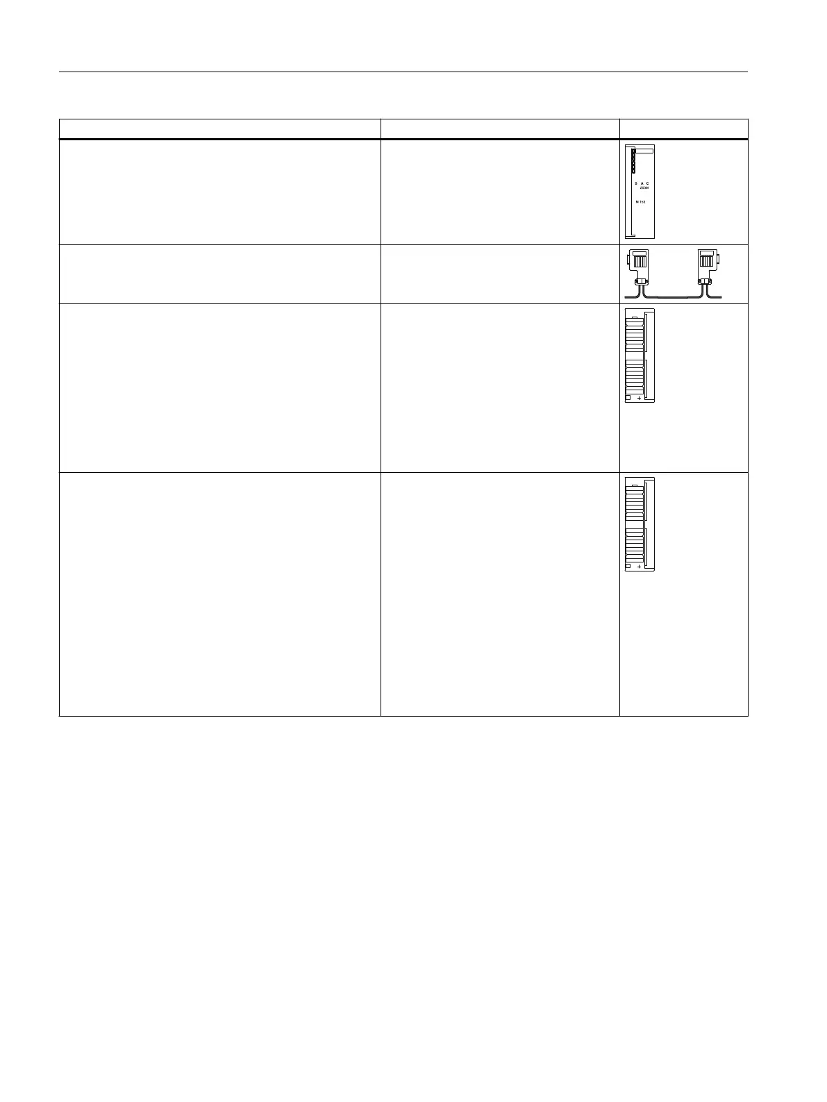
Component Function Diagram
IM 650
Accessories:
● Slot number plate (for the assignment of slot numbers)
... is the interface module; links the ET
200PA SMART I/O modules to the CPU
410 via PROFIBUS DP; supplies the back‐
plane bus with operating voltage.
PROFIBUS cable with bus connector ... combines nodes of a PROFIBUS DP
configuration with each other.
ET 200PA SMART I/O modules
Accessories:
● Front connector 20-pin
6ES7392-1AJ00-0AA0 or 6ES7392-1BJ00-0AA0
● Front connector 40-pin
6ES7392-1AM00-0AA0 or 6ES7392-1BM01-0AA0
● Front connector 20-pin for increased accuracy of
thermocouple measurement
6ES7392-1AJ20-0AA0
Digital and analog modules of the ET
200PA SMART
S7-300 I/O modules
Accessories:
● Front connector 20-pin
6ES7392-1AJ00-0AA0 or 6ES7392-1BJ00-0AA0
● Front connector 40-pin
6ES7392-1AM00-0AA0 or 6ES7392-1BM01-0AA0
● Front connector 20-pin for increased accuracy of
thermocouple measurement
6ES7392-1AJ20-0AA0
● Labeling sheets for 20-pin connector
6ES7 650-8XA00-0AA0
● Labeling sheets for 40-pin connector
6ES7 650-8XA10-0AA0
… supported modules from the S7-300
series of modules
See also
Arrangement of the modules for the function "Change During Operation" and / or "Redundancy"
(Page 20)
Configuring the electrical structure (Page 22)
Product overview
1.3 ET 200PA SMART Distributed I/O device
ET 200PA SMART
16 Operating Instructions, 06/2019, A5E34192013-AB
 Loading...


