2.2.3 Arrangement of the modules for the function "Change During Operation" and / or
"Redundancy"
Arrangement rules
The following rules apply to the arrangement of the modules in an ET 200PA SMART:
● An ET 200PA SMART must be mounted on one rack only (mounting rail). It is not permitted
to use interface modules to connect to other racks.
● You can plug a maximum of 12 modules to the right of the IM 650.
● You must plug the IM 650 and all modules into active bus modules.
Note
The active bus modules 6ES7650 8PA00-xAA0 and 6ES7650 8PB00-xAA0 have yellow
markings for easier identification. The purpose of these markings is to indicate that only IM 650
interface modules may be plugged into these bus modules.
● Use the mounting rails for "Module replacement in runtime" (only these allow mounting of
the active bus modules).
● Close unused slots with the backplane bus cover. Close the last bus module with the bus
module cover. The bus module cover is included with the bus module BM PS/IM or BM IM/
IM. The backplane bus cover has to be ordered.
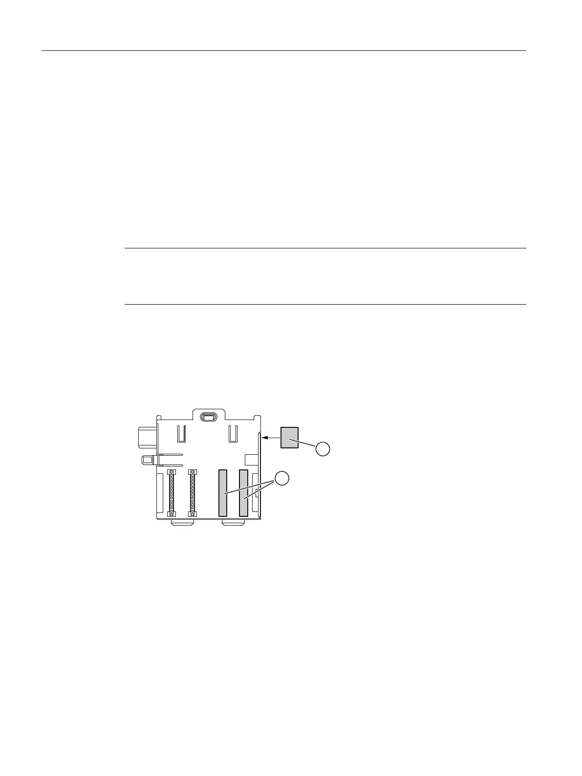
① Bus module cover
② Backplane bus cover
Figure 2-3 Example: Bus module 2 x 40 (6ES7 650 8PC00-0AA0)
● To use the ET 200PA SMART in the intrinsically safe area, use the Ex partition - preferably
between the modules in the intrinsically safe area and the modules in the non-intrinsically
safe area.
Restrictions
Use of the high-accuracy time stamp (1 ms accuracy) is only possible with 8 modules. In the ET
200PA SMART, you may use a maximum of 8 input modules after the IM 650 interface module
for this.
Assignment planning
2.2 Configuring the mechanical structure
ET 200PA SMART
20 Operating Instructions, 06/2019, A5E34192013-AB
 Loading...


