The default settings apply when you have not assigned parameters in HW Config or you have
not changed any parameters.
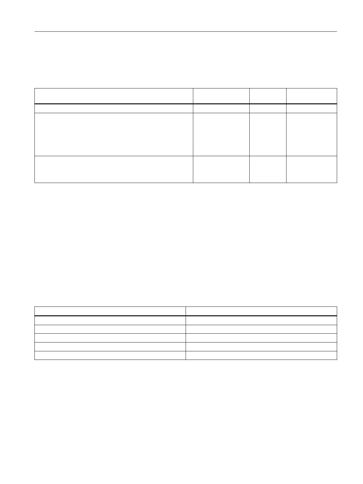
Table 10-2 Parameters of the DI 16 x DC 24 V
Parameter Value range Default set‐
ting
Scope
Diagnostic interrupt enable Yes / No Yes Module
Input delay 0.1 ms
0.5 ms
3 ms
15 ms
20 ms
3 ms Module
Diagnostics
● No sensor supply
● Wire break
Yes / No
Yes / No
Yes
Yes
Channel
Channel
Assignment of the sensor supplies to channel groups
The 2 sensor supplies of the module are used to supply two channel groups: inputs 0 to 7 and
inputs 8 to 15. You also assign the diagnostics for the sensor supply in these channel groups.
Group diagnostics
The diagnostics parameter "Group diagnostics" enables the signaling of channel-specific
errors to be switched off, with the exception of parameter assignment errors.
Tolerances of the assignable input delays
Table 10-3 Tolerances of the input delays of the DI 16 x DC 24 V
Assigned input delay Tolerance
0.1 ms 60 μs to 140 μs
0.5 ms 400 μs to 900 μs
3 ms (default) 2.6 ms to 3.3 ms
15 ms 12 ms to 15 ms
20 ms 17 ms to 23 ms
10.2.2.2 Diagnostics of the DI 16 x DC 24 V
Introduction
Module faults and channel faults are displayed via the group error display (SF LED) and
signaled via the diagnostic data records 0/1.
ET 200PA SMART I/O modules
10.2 Digital input modules
ET 200PA SMART
Operating Instructions, 06/2019, A5E34192013-AB 135
 Loading...


