Installing the shield connection element
Install the shield connection element as follows:
1. Push the two threaded bolts of the fixing bracket into the guide on the underside of the
mounting rail. Position the fixing bracket under the modules to be wired.
2. Screw the fixing bracket into place on the mounting rail.
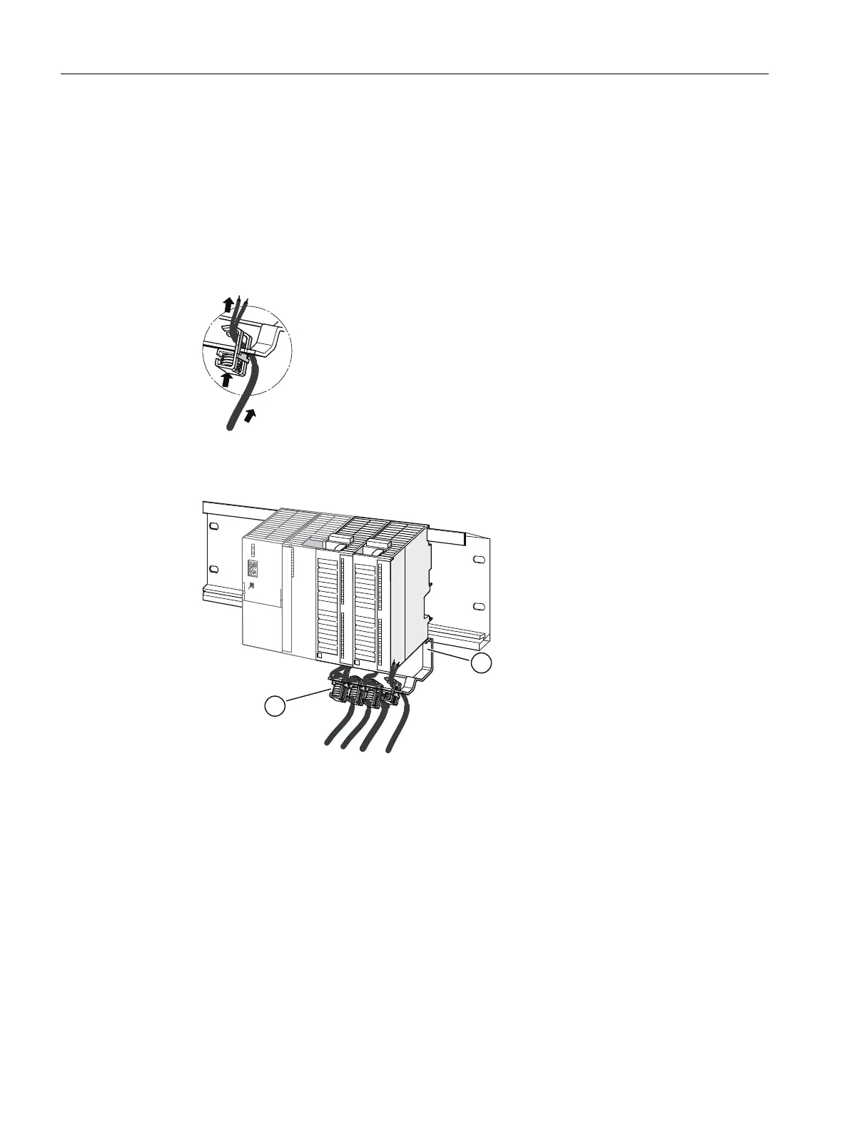
3. A slotted web is arranged at the bottom side of the shield connection clamp. Place the shield
connection clamp at this position onto the edge of the fixing bracket (see the figure).
4. Press the shield connection clamps down and swing them into the desired position.
You can attach up to 4 shield connection clamps on each of the two rows of the shield
connection element.
① Fixing bracket
② Shield connection clamps
Figure 4-3 Fitting the shielded 2-wire cables to the shield connection element
Connecting
4.3 Wiring the power supply and modules
ET 200PA SMART
50 Operating Instructions, 06/2019, A5E34192013-AB
 Loading...


