Mounting rail for active bus module
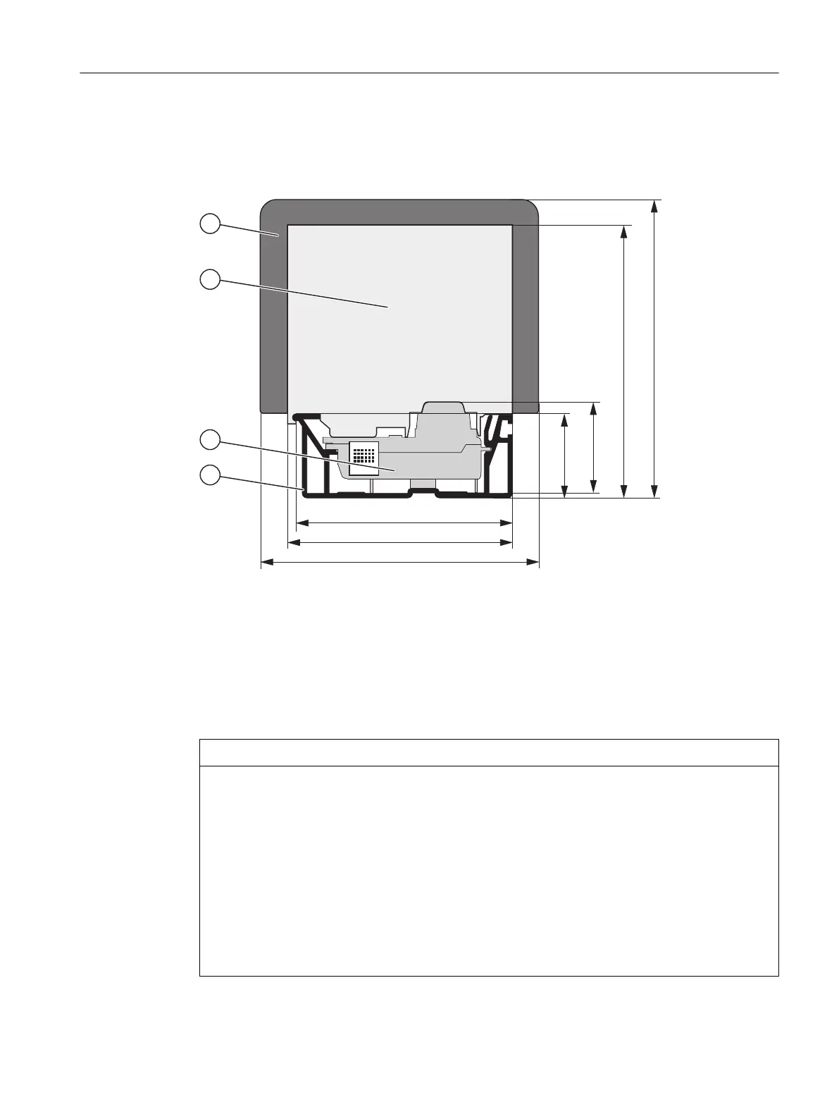
The figure below shows the dimension drawing of the mounting rail with active bus module, ET
200PA SMART module and Ex partition. The mounting rail is 482.6 mm or 530 mm long.
① Ex partition
② ET 200 PA SMART module
③ Active bus module
④ Mounting rail for the "Insertion and Removal" function
Plugging in output modules in a "running" ET 200PA SMART configuration
NOTICE
Uncontrolled system states
Uncontrolled system states may cause property damage.
Plugging in output modules can lead to uncontrolled system states!
This also applies if you insert input/output modules tilted on the bus module.
When plugging in an output module, the outputs set by the user program become active
immediately!
For pulling out an output module, set the outputs to "0" in the user program.
If modules are pulled and plugged incorrectly, neighboring modules may be disturbed through
the backplane bus.
Installation
3.2 Installation
ET 200PA SMART
Operating Instructions, 06/2019, A5E34192013-AB 37
 Loading...


