Only install the active bus modules in a de-energized state.
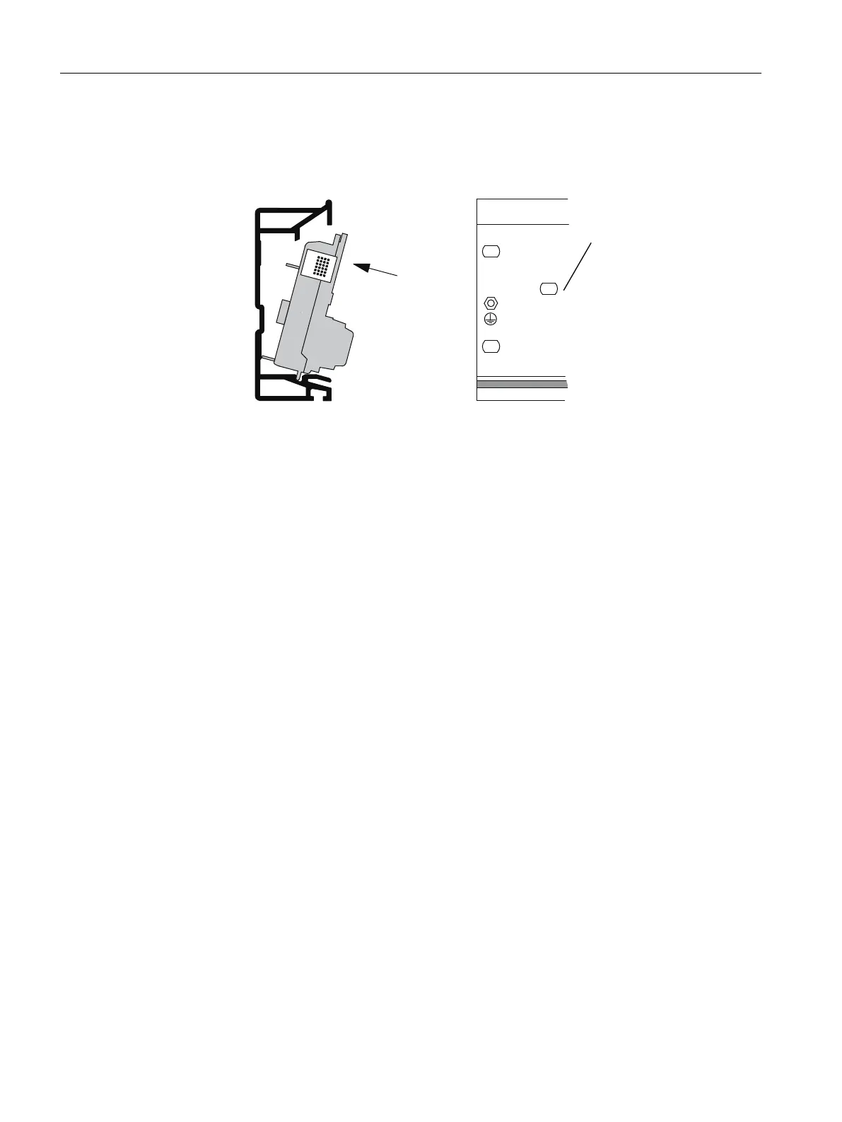
1. Hook the lower edge of the bus module BM PS/IM or BM IM/IM in the rail, and then press the
module into the rail (a) and slide it to the left up to the latched position (b).
Are you using the 530 mm mounting rail and the BM IM/IM?
If you position the BM IM/IM in the rightmost of the two latched positions (1), you can also
install either 2 x PS 307; 2A or 1 x PS 307; 5A to the left of the BM IM/IM.
2. Hook the next bus module (bus module BM 2 x 40) into the rail and press it onto the rail. Slide
it towards the left bus module, so that the module connector has contact.
3. Are you installing the ET 200PA SMART in intrinsically safe areas?
If yes, then you require the Ex partition between the modules in the intrinsically safe and the
non-intrinsically safe areas. To do this, simply insert the Ex partition on the right lateral guide
of the bus module.
4. Hook the modules into the rail and swing them down into place. Use the side guides of the
bus modules to do so. When you screw in the modules, you fix the bus module to the
mounting rail at the same time
5. Plug the bus module cover onto the last bus module. If there is a slot with no module, also
plug in the backplane bus cover on the unoccupied slot.
Installation
3.2 Installation
ET 200PA SMART
36 Operating Instructions, 06/2019, A5E34192013-AB
 Loading...


