Hardware interrupt of digital input modules
%\WH[
%\WH[
(GJHFKDQJHFKDQQHORIWKHPRGXOH
(GJHFKDQJHFKDQQHORIWKHPRGXOH
(GJHFKDQJHFKDQQHORIWKHPRGXOH
(GJHFKDQJHFKDQQHORIWKHPRGXOH
(GJHFKDQJHFKDQQHORIWKHPRGXOH
(GJHFKDQJHFKDQQHORIWKHPRGXOH
%\WHV[DQG[0RGXOHVSHFLILFLQIRUPDWLRQ
UHIHUWRWKHGHVFULSWLRQRIWKHUHVSHFWLYHPRGXOHV
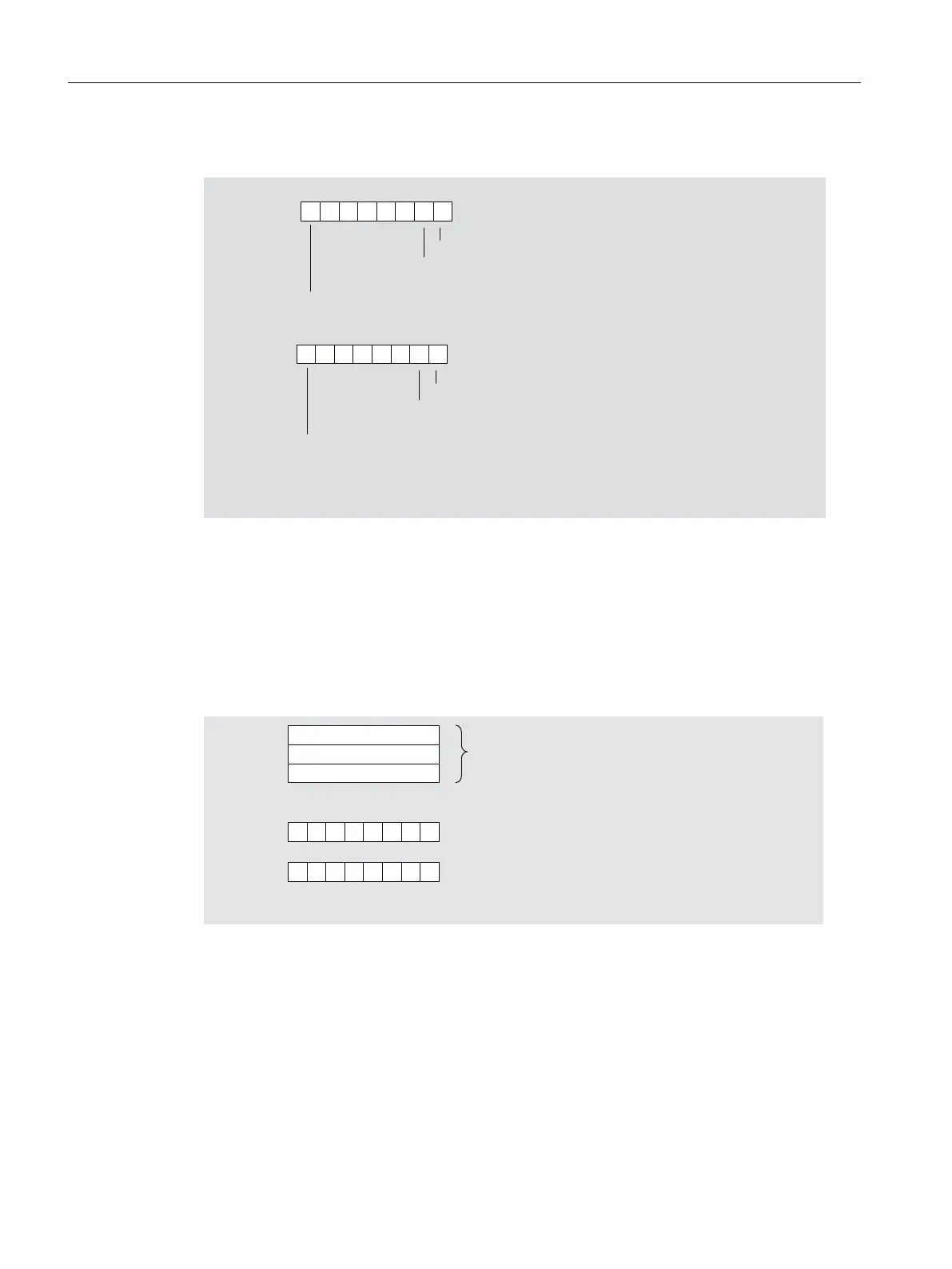
Figure 8-16 Structure starting from byte x+4 for hardware interrupt (digital inputs)
Plug/pull interrupt
You can identify whether the module has been plugged or pulled from the interrupt type in byte
x+1.
Bytes x+4 to x+8 contain an internal identifier (module identifier) of the module that was plugged
or pulled.
%\WH[
%\WH[
%\WH[
%\WH[
%\WH[
1RWUHOHYDQW
7\SHLGHQWLILFDWLRQRIWKH
PRGXOHKLJKE\WH
7\SHLGHQWLILFDWLRQRIWKH
PRGXOHORZE\WH
Figure 8-17 Structure starting from byte x+4 for plug/pull interrupt
See also
Structure of slave diagnosis (Page 91)
Arrangement of the modules for the function "Change During Operation" and / or "Redundancy"
(Page 20)
Interrupt, error and system messages
8.3 S7 diagnostics
ET 200PA SMART
114 Operating Instructions, 06/2019, A5E34192013-AB
 Loading...


