Technical specifications IM 650
● Time stamp ● Per digital input
● Per digital input module
● Entire ET 200PA SMART
● Time stamp in the case of
Rising/falling edge as incoming or outgoing signal
● Time format
RFC 1119 Internet (ISP)
Voltages, currents, electrical potentials
Rated voltage 24 V DC (20.4 to 28.8 V DC)
Current consumption from 24 V Max. 650 mA
Inrush current 3.0 A
Power on the I/O bus
(to supply the I/O modules)
Max. 1.5 A
I
2
t 0.1 A
2
s
Recommended external fusing for supply cables In a configuration with grounded reference potential
a fuse is required for redundant interface modules
(recommendation: 2.5 A).
Power loss, typ. 5.5 W
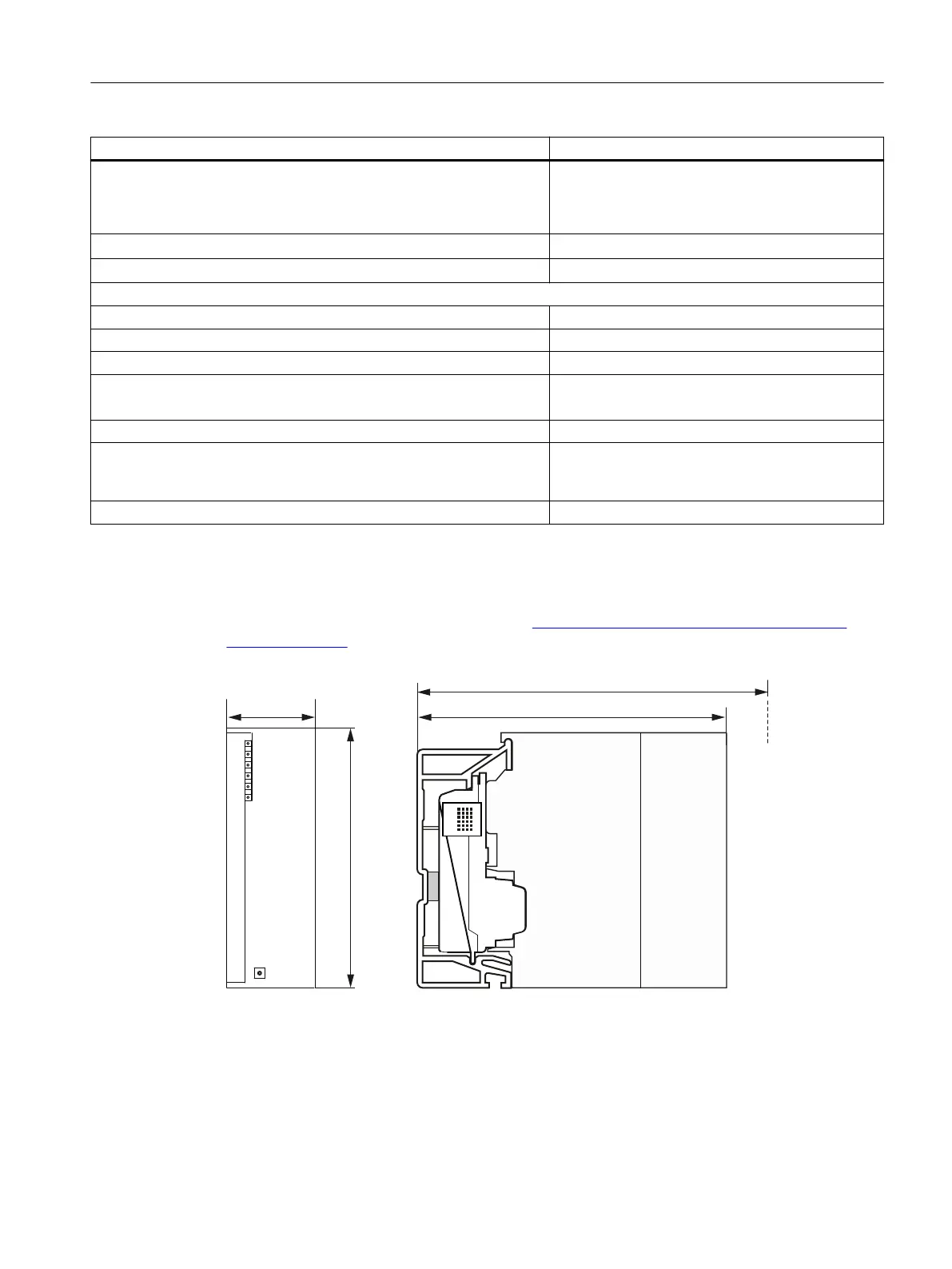
Dimension drawing for IM 650:
You can find a dimension drawing with the rail for the active bus modules in the "S7-300
automation system, module specifications (http://support.automation.siemens.com/WW/
view/en/8859629)" Reference Manual.
ZLWKIURQWGRRURSHQHG
Figure 9-1 Dimension drawing for IM 650
Interface module IM 650
9.2 Technical specifications of the IM 650
ET 200PA SMART
Operating Instructions, 06/2019, A5E34192013-AB 119
 Loading...


